
 Aktif Konular
  Üye Listesi
  Takvim
  Arama
Arama |
Aktif Konular Üye Listesi Takvim Arama |
| |
| Tayyareler | |
| |
  |
| << Önceki Sayfa 4 Sonraki >> |
| Yazar | Mesaj |
|
Nick_Karatzides
Üye 

Kayıt Tarihi: 06/06/2009 Aktif Durum: Aktif Değil Gönderilenler: 250 |
  Gönderim Zamanı: 21/02/2016 Saat 15:29 Gönderim Zamanı: 21/02/2016 Saat 15:29 |
|
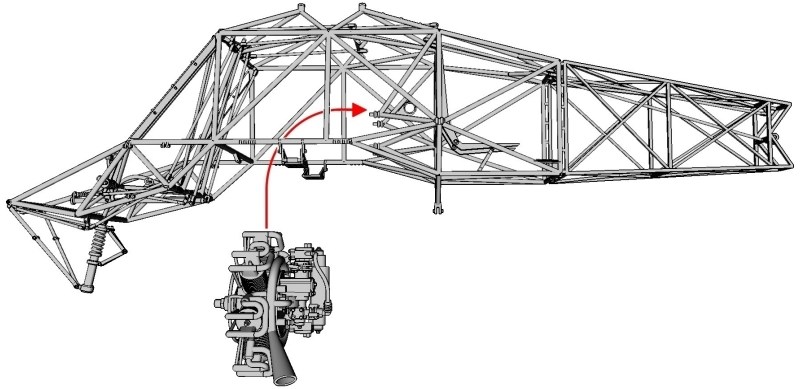
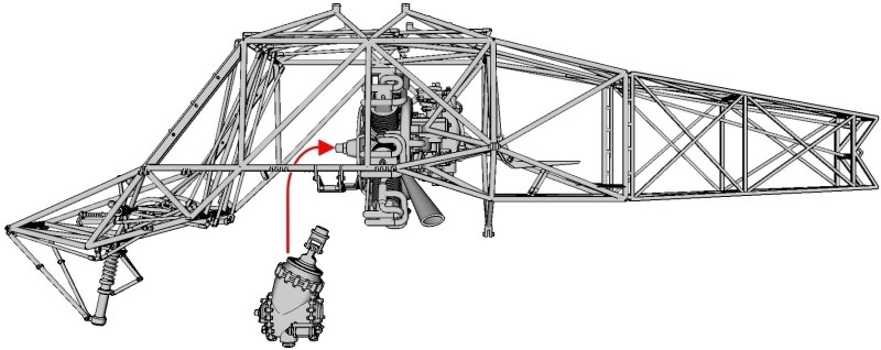
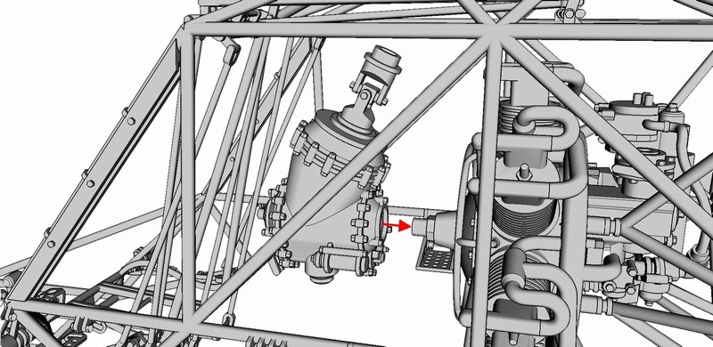
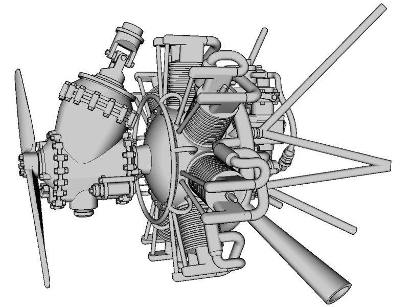
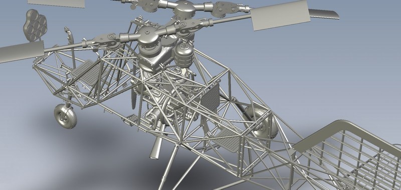
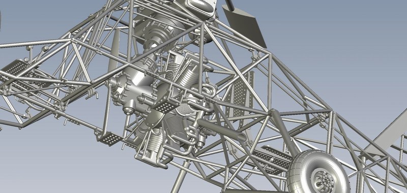
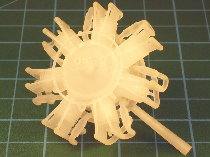
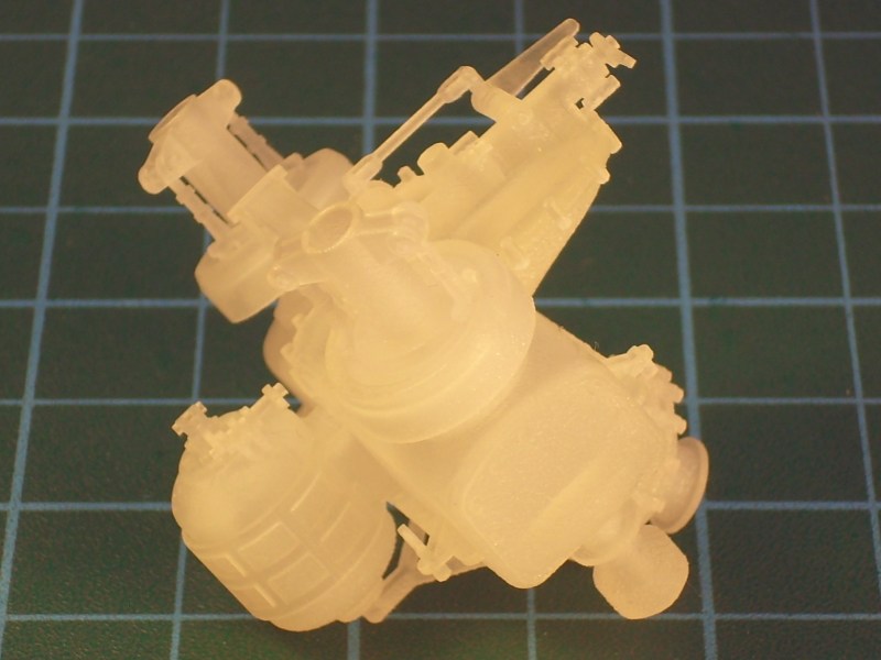
When powerplant paintjob looked OK to me, it was about time to attempt mounting both 7-cylinder radial engines as required - the first one onto helicopters tubular frame and the second one placed on the wheeled stand. As described into through pages #8 to #14 of the ultra-detailed 1/18 Fl-282 V21 kit building instructions manual (which can be found HERE as a downloadable PDF format file), the radial engine carefully inserted underneath the main tubular frame and placed in such way to align the engines four slots right onto the frames support beams. Since the nearby battery brackets were too fragile (only 0.4 mm thick), I had to avoid violent moves while installing engine to prevent plastic fracture. As soon as the four slots were simultaneously aligned onto the support beam heads, the engine slided backwards and secured in place by adding a drop of cyanoacrylate super glue.
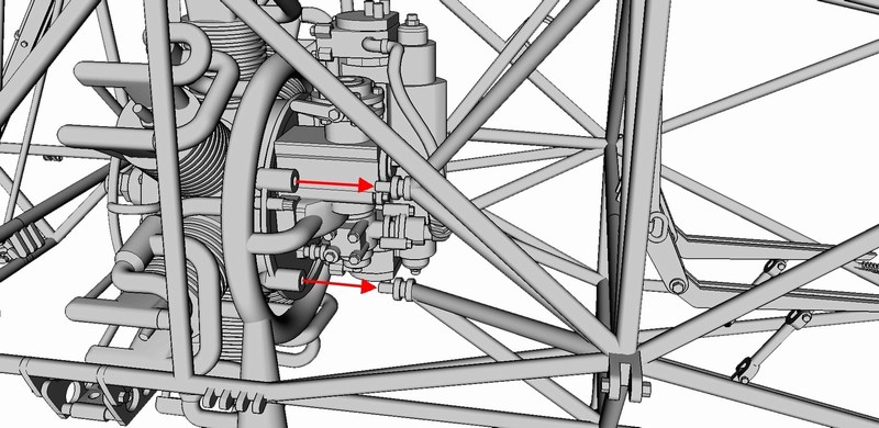 The drive shaft inserted into the transmission units upper opening as shown on the following pictures. The drive shaft designed as a mirrored part and therefore it can be installed either on one side or the other - no matter which side is the top and which is bottom. The transmission unit should be placed on the front of the engine block from which the drive shaft ran to upper gearbox. To do so, the block carefully inserted underneath the main tubular frame, placed in such way to align transmissions rear opening against the 7-cylinder radial engines front end and secured in place by adding a drop of cyanoacrylate superglue. 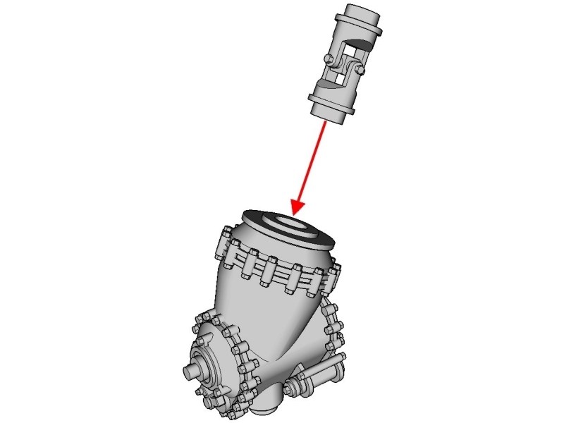
 Düzenleyen Nick_Karatzides - 27/07/2018 Saat 12:29 |
|
 |
|
|
Nick_Karatzides
Üye
Kayıt Tarihi: 06/06/2009 Aktif Durum: Aktif Değil Gönderilenler: 250 |
Gönderim Zamanı: 21/02/2016 Saat 15:34 |
|
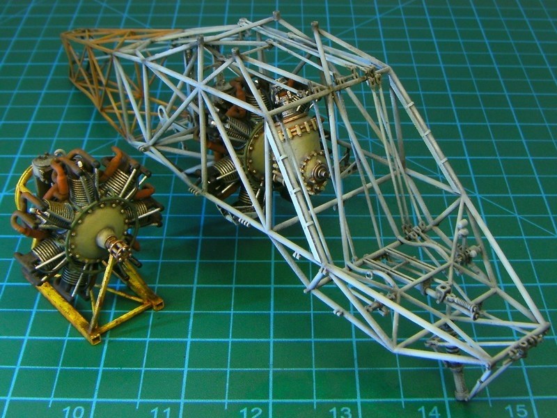
Well, it took approx 230 pictures and several thousand text words so far, to present the first actual plastic-to-plastic CA gluing. As previously mentioned into CHAPTER III, I prefer to follow the paint individual parts first and assemble model later rule, since I find it more appropriate and surely make my life easier. Seems like the WIP turns from CAD to traditional modeling now, isnt it?
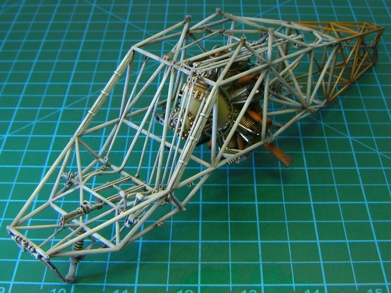
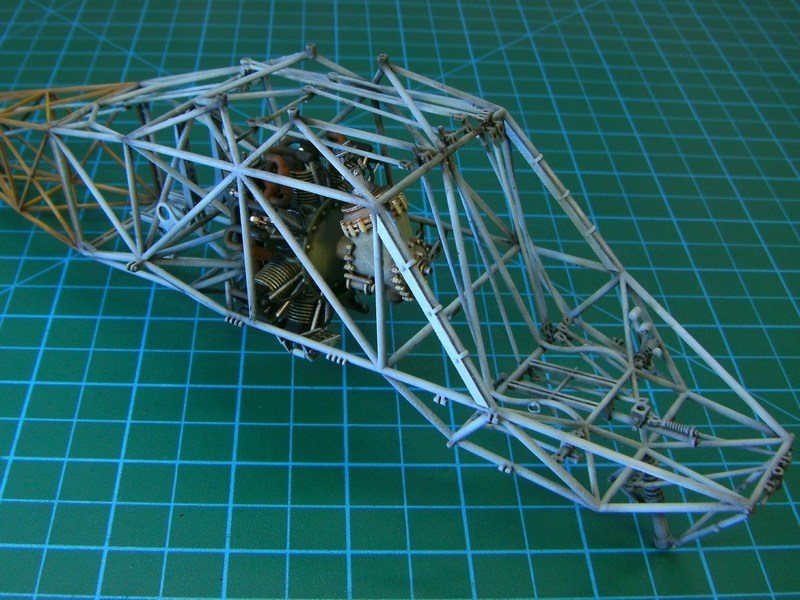
 The wheeled stand for 2nd engine, also got painted with some random yellow acrylic paint and later weathered to look paint scraped, with faint areas of rust and a lot of dirt & oil stains. 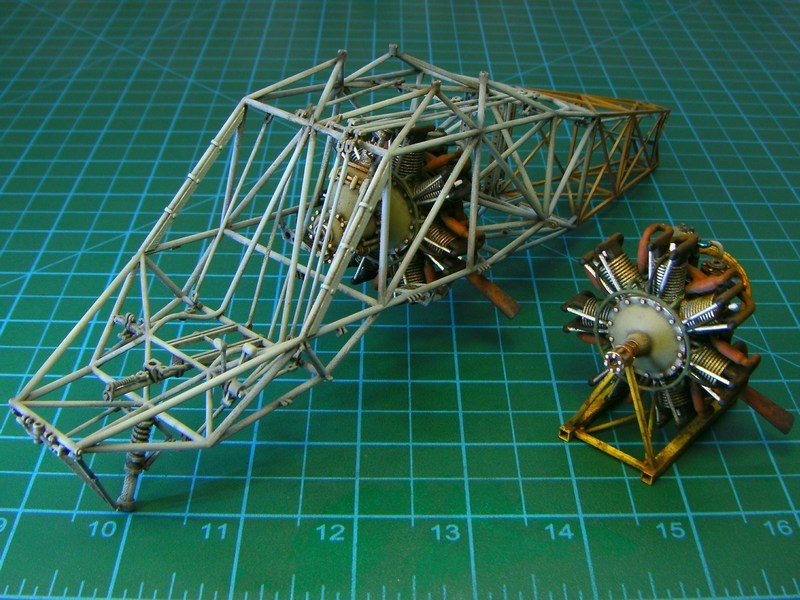
 Düzenleyen Nick_Karatzides - 27/07/2018 Saat 12:30 |
|
|
|
|
|
Nick_Karatzides
Üye
Kayıt Tarihi: 06/06/2009 Aktif Durum: Aktif Değil Gönderilenler: 250 |
Gönderim Zamanı: 04/03/2016 Saat 05:35 |
|
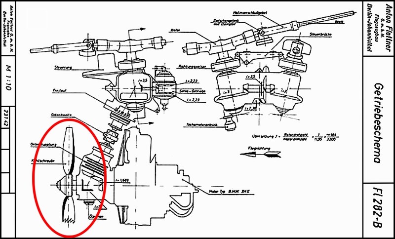
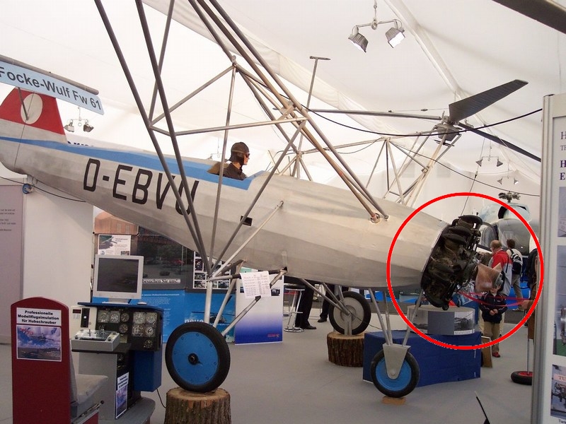
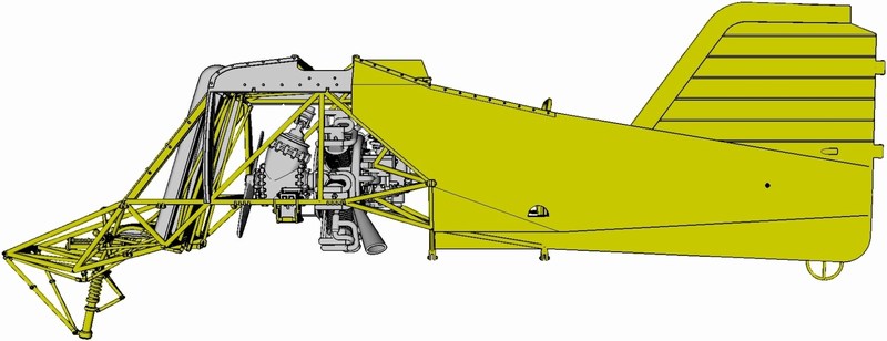
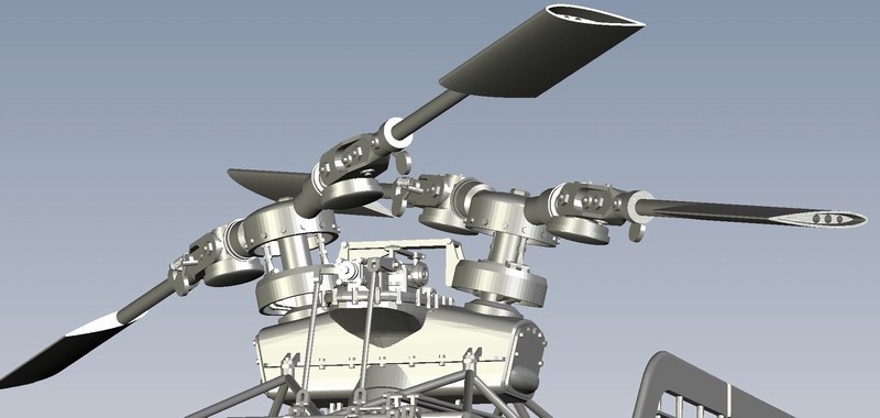
The engines cooling fan, proved to be the most controversial part of the kit. What really happened? Well, first things first: The Kolibri helicopter was equipped with an air-cooled 7-cylinders radial engine located inside the fuselage center-section and enclosed by outer skin. The powerplant should be efficiently cooled somehow to ensure proper & continuous operation. To do so, air was drawn in through openings beneath the fuselage by a wooden cooling fan with direct drive from powerplant provided strong air flow towards engines cylinders.
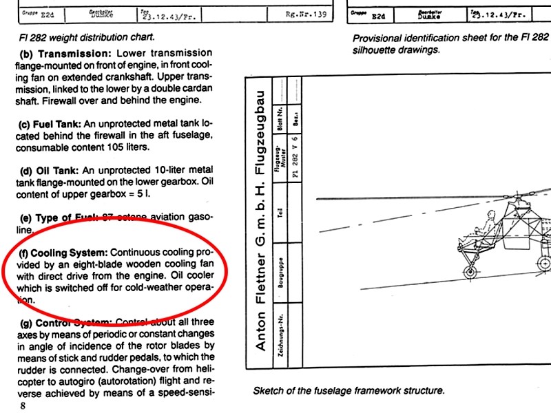
 Despite the fact that Luftwaffe Profile Series #6 Flettner Fl 282 ISBN 0-88740-921-0 book (released on 1996 by Schiffer Publishing, written by Theodor Muhr and originally publilshed on 1991 by Flugzeug Publikations GmbH under the title Flugzeug Profile Flettner Fl 282 Kolibri Varianten) says that continuous cooling provided by an eight-blade wooden cooling fan with direct drive from the engine (page #8), I could not find any front head view photograph of the so-called 8-bladed cooling fan. 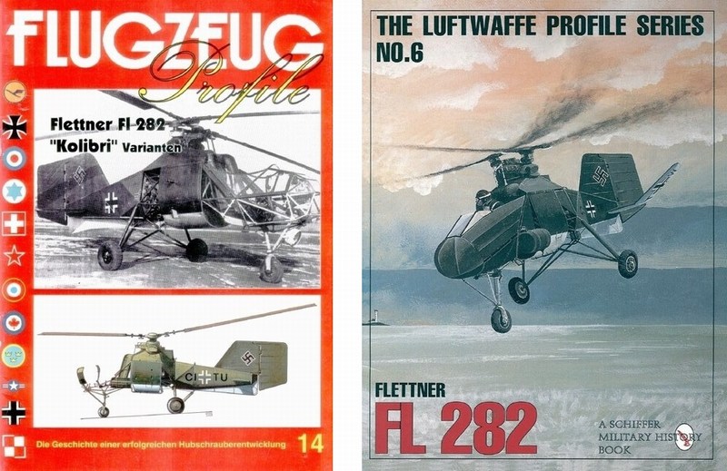
 On the other hand, Ryszard Witkowski author of the Rotorcraft of 3rd Reich #5109 ISBN 978-83-89450-43-2 book (released on 2006 by MMP - Mushroom Model Publications), says that the engine was cooled by a wooden twelve-blade fan (page #24), which further complicates the question on the cooling fan issue. So, what type of cooling fan was actually fitted in front of the air-cooled 7-cylinders radial engine? Was it a 8-bladed wooden propeller or a 12-bladed? Or maybe none of the above? 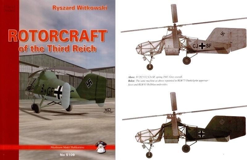
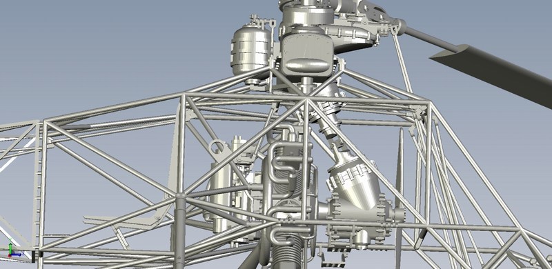
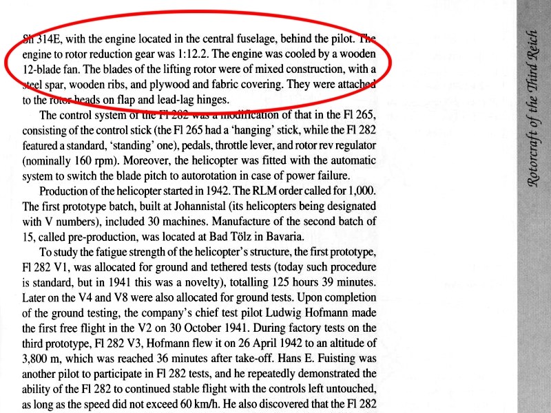 To make things worst, the available diagrams are side-viewed and its not easy to say if the cooling fan is 2-bladed, 10-bladed or 50-bladed. IMHO, when it comes to cooling issue, I think that a multi-bladed fan would be more appropriate. Although a 6-bladed cooling fan had already been used on Flettner Fl-265 helicopter, the Deutsches Museum officials deny the 8-bladed or 12-bladed fan claim and they strongly support the 2-bladed propeller 90 cm Ø version - after all, they supposed to know better about Flettner 282, dont they? 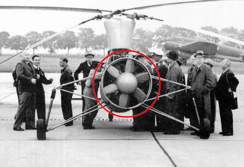 Furthermore, I spotted more errors and incorrect assumptions into the pages of the aforementioned books, which further strengthens my doubts about the accuracy of the given information. For example, it is written that Flettner 282 had not functional elevators and they were just dummy horizontal stabilizers bolted to fuselage frame, which is a huge mistake because blueprints, actual pictures & videos show the exact opposite. Also, it is written that all Kolibris from V20 to V24 versions were completed as two-seaters, which is also a false claim, according to Luftwaffes WWII and Anton Flettner Flugzeugbau GmbH files. Anyway, since I had not a clear evidence of an 8-bladed or a 12-bladed wooden propeller use on Kolibri helicopter and having in mind that both above mentioned books had already few mistakes written into pages, the multi-bladed wooden propeller story seems a little questionable and the 2-bladed cooling fan version is considered as the most plausible, just like appeared on the Focke Wulf FW-61 helicopter which already had a single 2-bladed propeller for engine air cooling. I hope my estimations / guesswork are correct and I will not have to publicly perform seppuku because of shame. 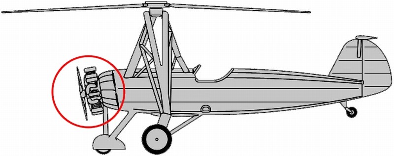
 Düzenleyen Nick_Karatzides - 27/07/2018 Saat 12:30 |
|
|
|
|
|
Nick_Karatzides
Üye
Kayıt Tarihi: 06/06/2009 Aktif Durum: Aktif Değil Gönderilenler: 250 |
Gönderim Zamanı: 04/03/2016 Saat 05:45 |
|
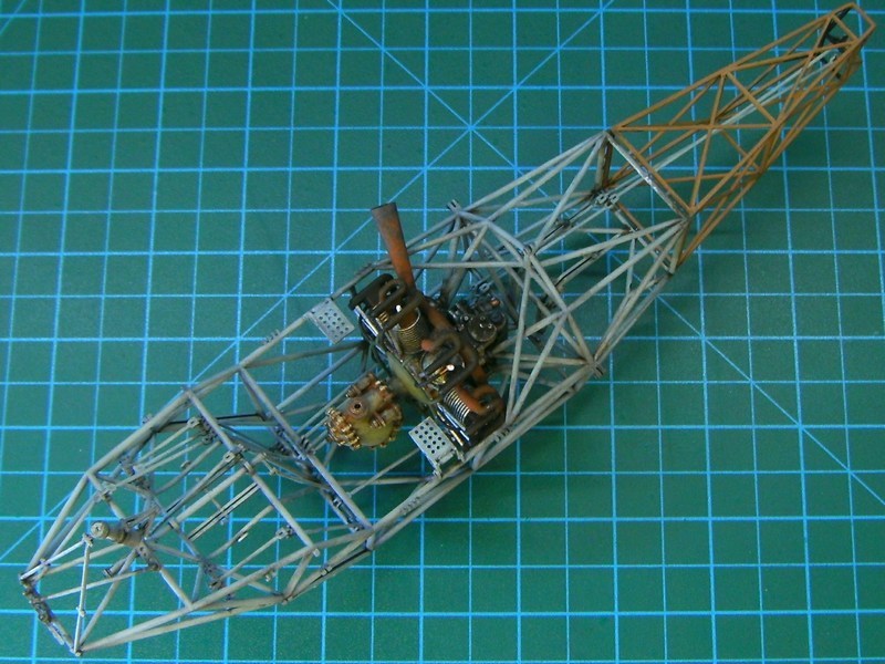
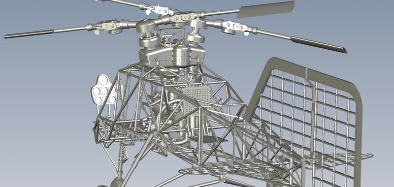
Once the radial engine mounting process completed, I would attempt to turn a pigs ear to silk purse - in other words, to paint the 3D printed cooling fan in such way to look like made of wood. Since (as commented into previous paragraphs) I had not enough reference of the actual Kolibris cooling fan, I did what most modelers always do - improvise, hoping that final result would look nice! To do so, I used the Life Color UA716 Wood Warm light shade 2 acrylic paint, to overall spray the 2-bladed propeller. Once the acrylic base coat has cured, I used artists oil paints - actually a mixture of Burnt Sienna, Yellow Ochre and Raw Umber in a ratio of 25% to 25% to 50% - to simulate the wood grain and spread a thick layer of paint around. At this point the oils will be workable for several hours. Then, while using a clean & completely dry broad, hard brush, I dragged it over the oil paint, leaving wood grain streaks. As the brush picked up the paint, I wiped it off on a clean, lint free cloth. I left it alone to dry for 24 hours.
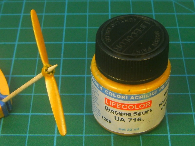
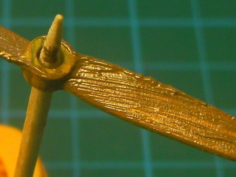
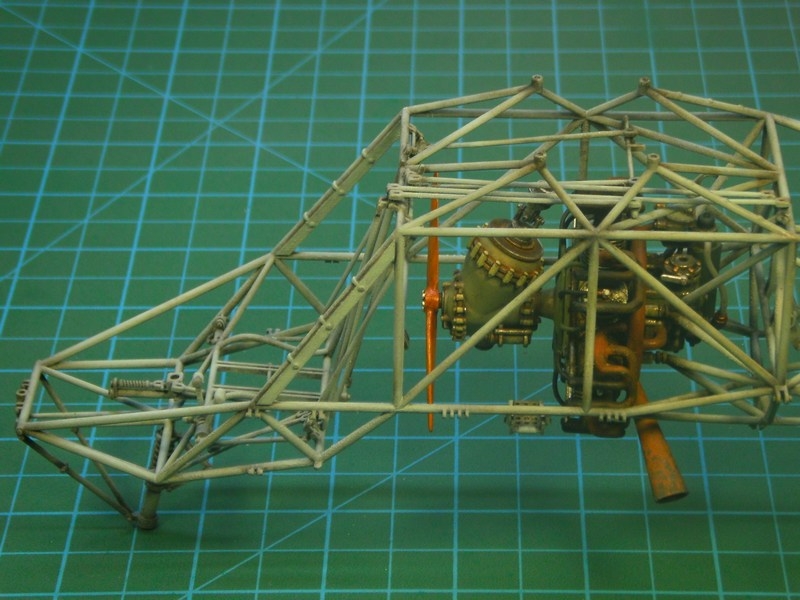
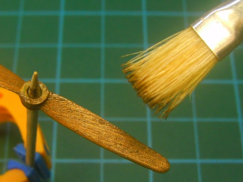 A day later, while oil paint was not fully dry, I used a clean soft brush to blend the streaks, just a little more. As soon as it looked OK to me, I left it few days more to dry completely and then spray it with Tamiya Color X-24 Clear Yellow acrylic, because it also helps bring the grain color out more. 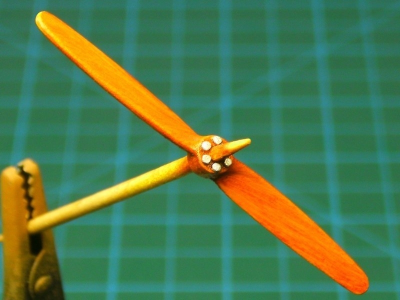 The 2-bladed wooden propeller placed on the front end of the (previously installed) transmission block. So, this is how the assembled block of 7-cylinder radial engine, transmission unit, drive shaft & cooling fan should look like when correctly fit into each other. 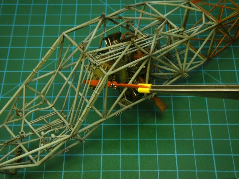
 Düzenleyen Nick_Karatzides - 27/07/2018 Saat 12:31 |
|
|
|
|
|
Nick_Karatzides
Üye
Kayıt Tarihi: 06/06/2009 Aktif Durum: Aktif Değil Gönderilenler: 250 |
Gönderim Zamanı: 07/03/2016 Saat 05:38 |
|
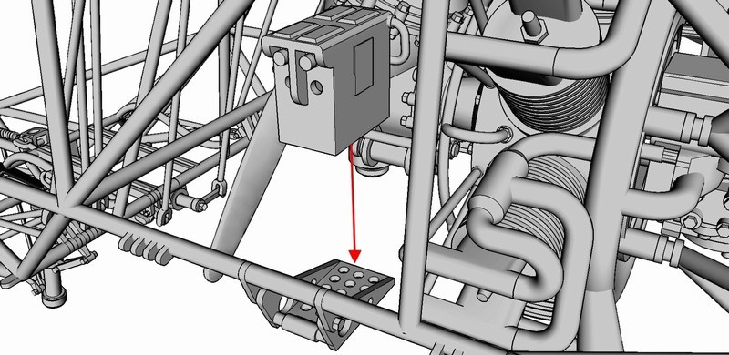
If the assembly sequence would follow the instructions by-the-book, the two battery packs should be placed on appropriate brackets located on either side of the transmission unit as shown in the picture from the kit manual. Since the original building idea requires to setup the 1/18 scale Kolibri model in such way to look like under maintenance (or refueling) procedure with all the hatches & sliding panels opened or removed, I decided to deviate just a little from the schedule and do something different: To unplug the batteries and place them somewhere else - possibly on some wooden box or the previously mentioned wooden ladder, one of these unrelated to the helicopter structure additional parts which were designed & 3D printed to be used as part of a diorama scene.
 Düzenleyen Nick_Karatzides - 27/07/2018 Saat 12:32 |
|
|
|
|
|
Nick_Karatzides
Üye
Kayıt Tarihi: 06/06/2009 Aktif Durum: Aktif Değil Gönderilenler: 250 |
Gönderim Zamanı: 07/03/2016 Saat 05:48 |
|
Each one of the 1/18 scale Flettner 282 V21 kits contains two crew seats for the pilot and for the rearwards facing observer. The observers seat consists of two perforated plywood boards, one for the bottom part fixed on a retractable bracket and one for the backrest fixed on frame rails. Cushions are placed over bottom part & backrest plywood boards to provide comfort. On the other hand, the pilots seat consists of a (similar cushion covered perforated plywood board) bottom part only, since he rests his back-pack type parachute against the front fuselage cover. 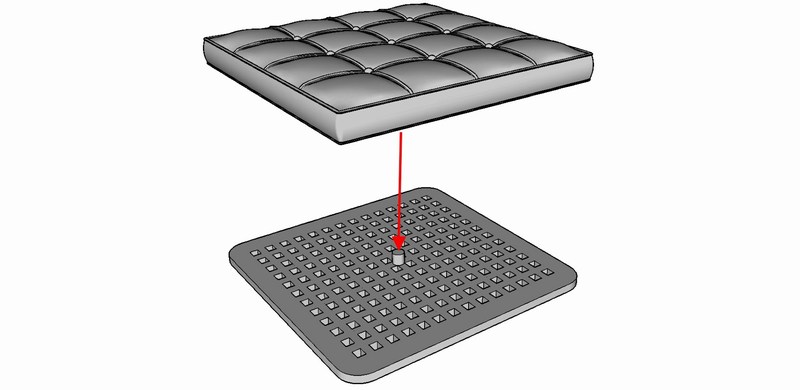
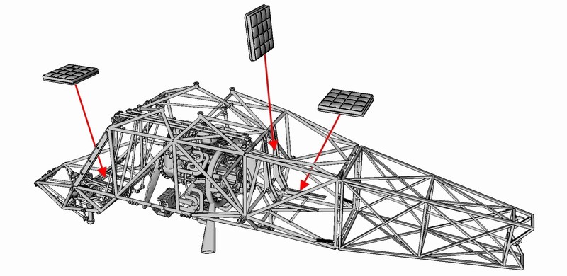 Having just painted the perforated plywood boards and being quite pleased with the outcome, I decided (once again) to deviate from the instructions and skip the cushions installation - after all, the reddish varnished look on plywood boards seems to make a fine contrast with the overall RLM 71 Dunkelgrün FS 34079 and breaks the green monotony. 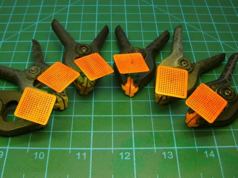
 Düzenleyen Nick_Karatzides - 27/07/2018 Saat 12:32 |
|
|
|
|
|
Nick_Karatzides
Üye
Kayıt Tarihi: 06/06/2009 Aktif Durum: Aktif Değil Gönderilenler: 250 |
Gönderim Zamanı: 07/03/2016 Saat 05:56 |
|
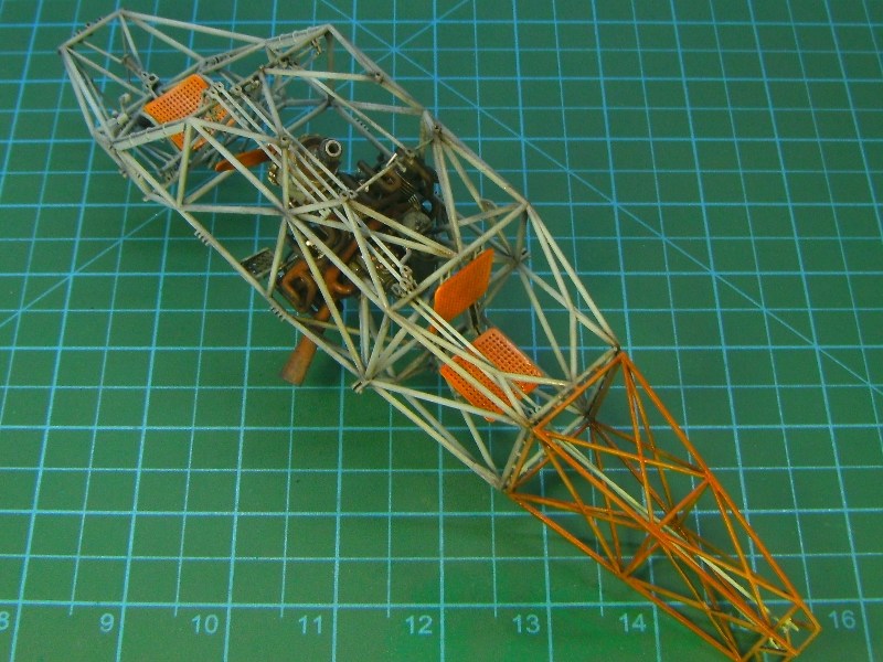
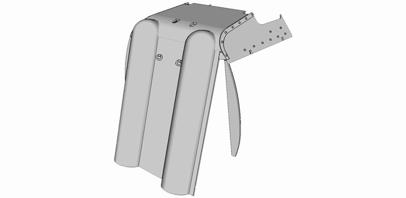
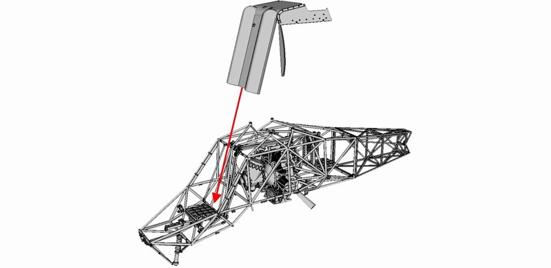
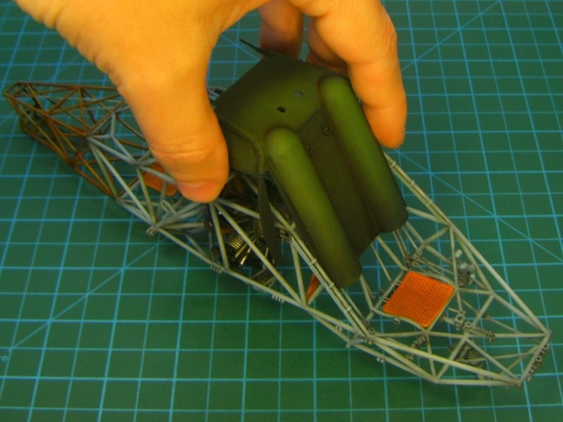
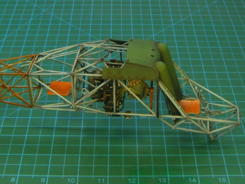
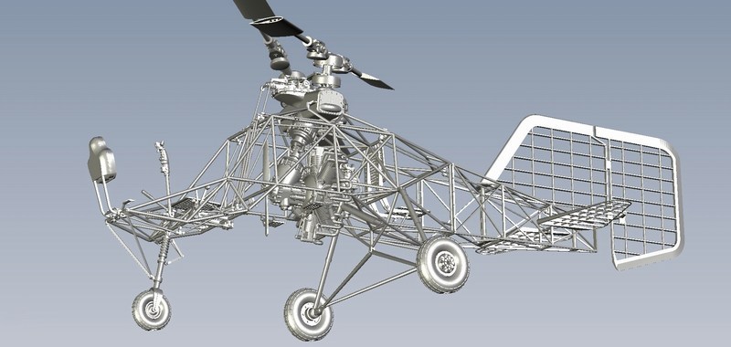
Those who have followed this thread from the start, will remember that the front fuselage cover had already been covered with an overall dark undercoat and later gradually airbrushed with RLM 71 Dunkelgrün FS 34079 to achieve proper gradations of light. The front fuselage cover patiently awaited the tubular frame painting completion, in order to come the turn to be properly installed. The part carefully dragged in place along the frame tubes, until reached down on the pilots seat & secured in place with a drop of cyanoacrylate super glue.
 Düzenleyen Nick_Karatzides - 27/07/2018 Saat 12:33 |
|
|
|
|
|
Nick_Karatzides
Üye
Kayıt Tarihi: 06/06/2009 Aktif Durum: Aktif Değil Gönderilenler: 250 |
Gönderim Zamanı: 09/04/2016 Saat 10:01 |
|
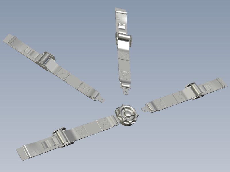
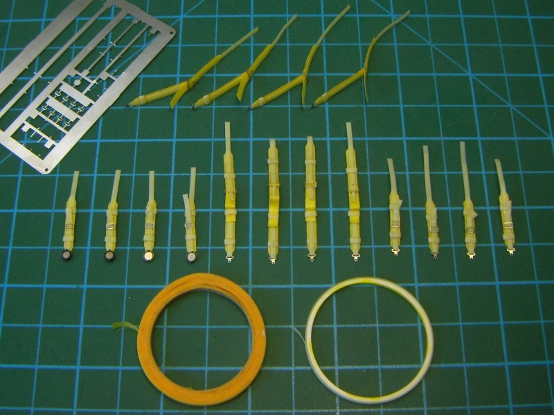
The first two production model kits under 1/18 scale, were 3D designed such way to have the seatbelts & buckles embossed on the crew seat cushions - a tactic that later altered, since customers mostly prefered to add their own harness or leave the miniature helicopter free of straps webbing. For this reason, the seatbelts shown into following pictures were built from 2.5mm to 3.5mm wide masking tape and photoetched set by Eduard, under 1/20 scale. The seatbelts later got some brownish & khaki paint - so as to make sharp & nice looking contrast against the reddish varnished plywood seatboards and the overall RLM 71 Dunkelgrün FS 34079 painted airframe cover.
 Düzenleyen Nick_Karatzides - 27/07/2018 Saat 12:34 |
|
|
|
|
|
Nick_Karatzides
Üye
Kayıt Tarihi: 06/06/2009 Aktif Durum: Aktif Değil Gönderilenler: 250 |
Gönderim Zamanı: 09/04/2016 Saat 10:12 |
|
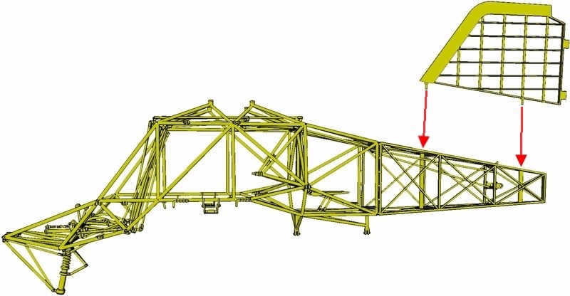
The rear fuselage section on real Flettner 282 helicopter was made of doped fabric covering over the steel and wooden frame. Those who have followed this thread from the start, will remember that the rear fuselage section had already been covered with an overall black / dark brown undercoat and then gradually lighten the surfaces to replicate the way that sunlight hits on large objects, following the Francois Verlindens old-fashioned way (which was re-introduced and become popular around the scale modelling community, by its new modulation name). The dark undercoat, gradually airbrushed with RLM 71 Dunkelgrün FS 34079 to achieve proper gradations of light, trying to balance between realism factor and artistic expression. IMHO modulation effect does not accurately replicate the reality, but it looks so artistically attractive and becomes easily accepted by our visual subconscious. Custom made water slide decals applied and later everything washed by brushing Winter Streaking Grime AK014 filter available by AK Interactive, until the desired colour density is achieved. As described into pages #25 to #27 of the ultra-detailed 1/18 Fl-282 V21 kit building instructions manual (which can be found HERE as a downloadable PDF format file), the rear fuselage cover part carefully dragged along the miniature's wooden frame, until reached down on the transmission pivots & secured in place with a drop of cyanoacrylate super glue. 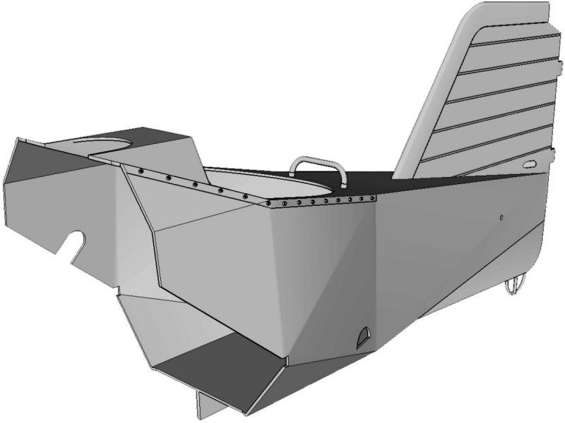
 Düzenleyen Nick_Karatzides - 27/07/2018 Saat 12:34 |
|
|
|
|
|
Nick_Karatzides
Üye
Kayıt Tarihi: 06/06/2009 Aktif Durum: Aktif Değil Gönderilenler: 250 |
Gönderim Zamanı: 11/04/2016 Saat 17:22 |
|
A year passed since April 11th 2015. A day like today and the whole World seems so empty when you miss your other half.
 Düzenleyen Nick_Karatzides - 27/07/2018 Saat 12:35 |
|
|
|
|
|
Nick_Karatzides
Üye
Kayıt Tarihi: 06/06/2009 Aktif Durum: Aktif Değil Gönderilenler: 250 |
Gönderim Zamanı: 11/04/2016 Saat 17:24 |
|
Orjinalini yazan: Nick_Karatzides
A year passed since April 11th 2015. A day like today and the whole World seems so empty when you miss your other half. Wishing to remember this day and honor her sweet & loving memory, last week Anyuta 3D decided to make an offer for few fellow modelers & skilled craftsmen by sending a limited number of coupons. During last week, few hand-picked forum members, specialy selected talented & promising modelers, received (or about to receive) their own 3D printed 1/18 scale Flettner Fl-282 Kolibri cutaway model kits. By the time these lines are written, the parcels are on their way to modelers postal addresses. 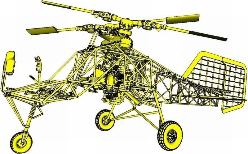
 Düzenleyen Nick_Karatzides - 27/07/2018 Saat 12:35 |
|
|
|
|
|
Nick_Karatzides
Üye
Kayıt Tarihi: 06/06/2009 Aktif Durum: Aktif Değil Gönderilenler: 250 |
Gönderim Zamanı: 14/04/2016 Saat 23:13 |
|
Steering of the Fl-282 was achieved by a combination of the rudder and differential collective pitch change on the two rotors, but only the rudder could give steering during autorotation since collective pitch was then ineffective (another reason for the large rudder area). Rudder fin (of very generous area), was made of wood and covered by fabric, with max 40° deflection left or right. This large area was necessary because much of it was ineffective due to the poor aerodynamic shape of the fuselage causing rearwards flow separation and turbulence. The vertical stabilizer and the elevators were also made of wood, with plywood leading edge and fabric covering, bolted to fuselage frame.
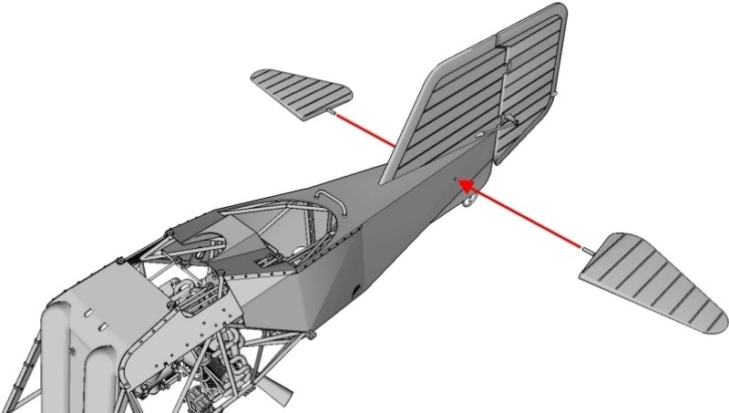
As described into pages #29 to #32 of the ultra-detailed 1/18 Fl-282 V21 kit building instructions manual (which can be found HERE as a downloadable PDF format file), the rudder fins slots should be aligned onto horizontal stabilizer's hinges as shown on the following pictures. I tried dry fit testing before the final gluing & part secured in place by adding a drop of cyanoacrylate superglue. Since the rudder fin can be instaled turned (with max 40° deflection left or right), the servo bars should be inserted into slots & placed as required. Notice that if the rudder fin is tilted left or right or neutral, the rudder pedals at cockpit area & nose wheel, should be also positioned accordingly. 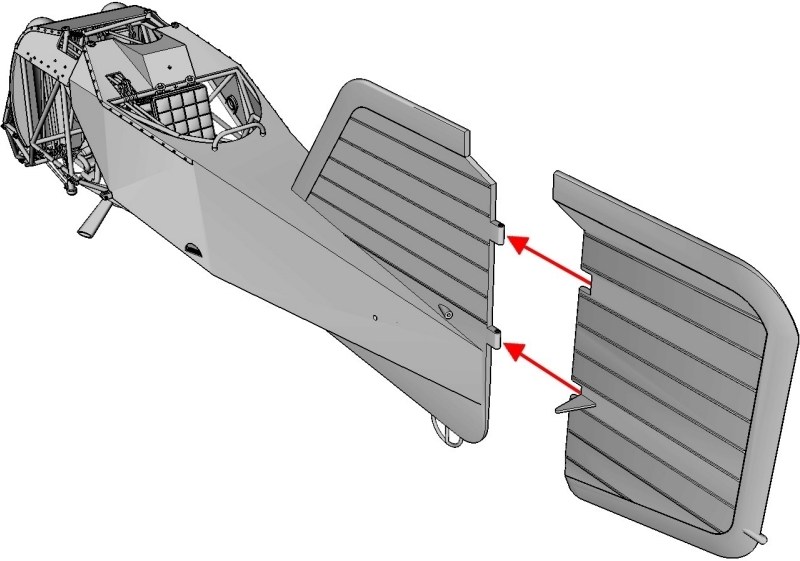
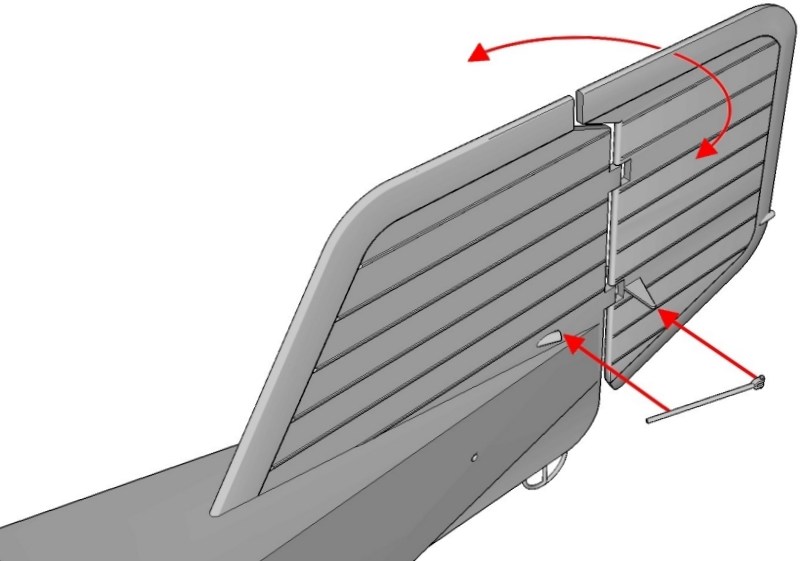
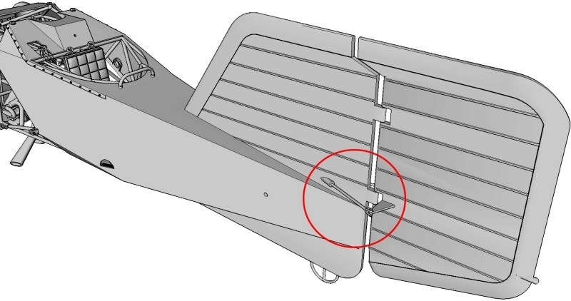 The two horizontial elevator fins should be installed by inserting the 1.4 mm Ø pins through side openings of rear fuselage section as shown on pictures and securing in place with a drop of cyanoacrylate superglue. Keep in mind that if the horizontial elevator fins are placed tilted up or down or neutral, the cyclic / KG.13 control stick at cockpit area, should be also positioned accordingly. 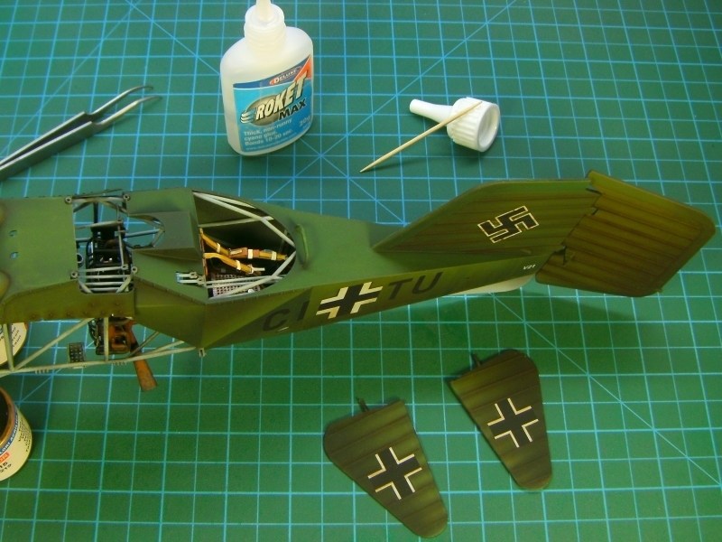
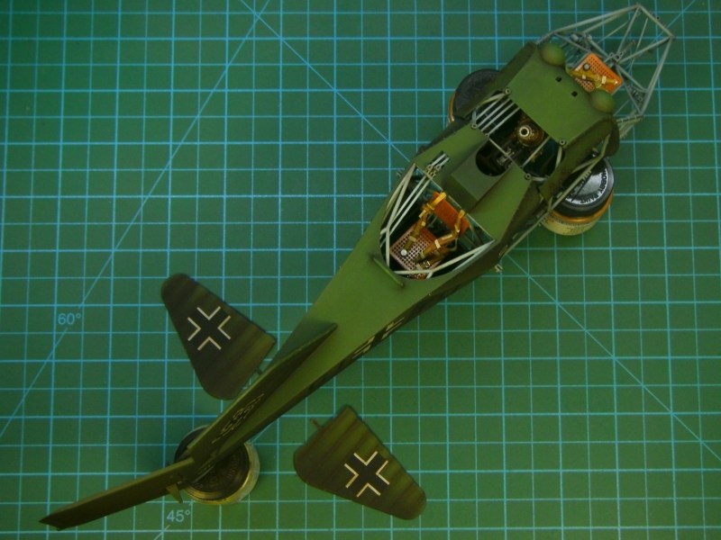
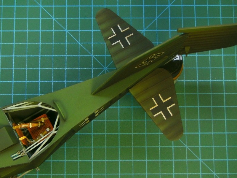 Under normal conditions, each helicopters registration ID was duplicated under elevator fins. After all, there are many photographic evidences certifying this feature, just like the following picture showing the CJ-SK registered Fl-282 V17 helicopter, crashed at Travemünde on April 13rd 1944, while test pilot FliegerStabsingenieur (Luftwaffe Major) Gerhard Geike was attempting a diving nose-down and then pulling back technique landing. 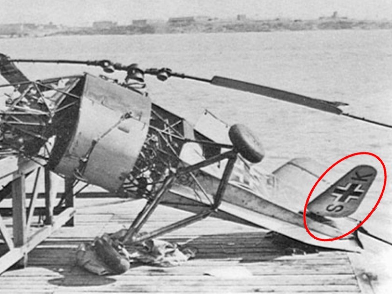 However, there is a rare photograph of the already mentioned CJ-SN registered Fl-282 V20 helicopter assigned to Staffel 1/196 at Pillau AB as found & captured by the British Army, that clearly shows registration missing under the elevator fins. Luckily, the picture taken before helicopter been brutally disassembled, doped fabric ripped away & removed from fuselage, clipped rotor blades cut off & never seen again since that day and remaining framework wreckage with upper rotor transmission parts transferred back to UK as a War trophy and ended up as souvenirs. 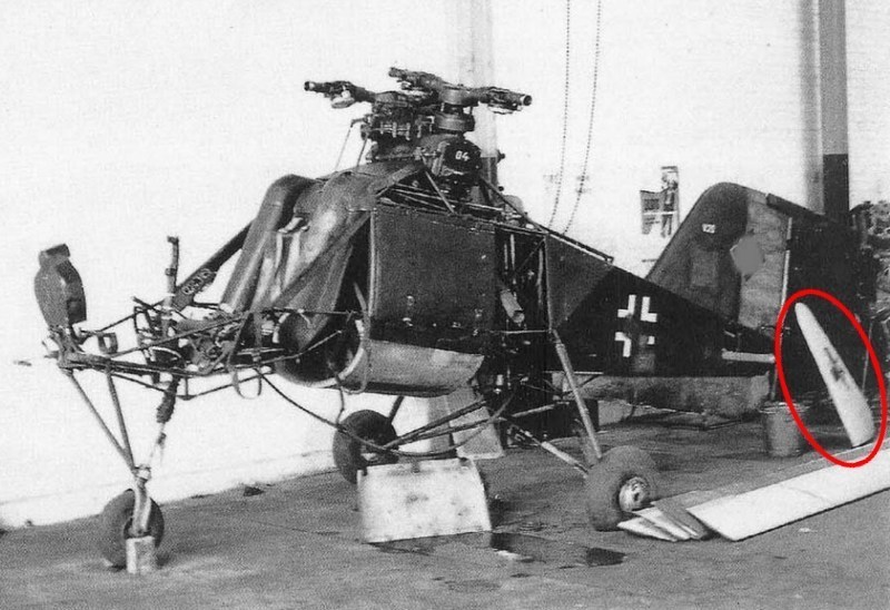 Düzenleyen Nick_Karatzides - 27/07/2018 Saat 12:36 |
|
|
|
|
|
Nick_Karatzides
Üye
Kayıt Tarihi: 06/06/2009 Aktif Durum: Aktif Değil Gönderilenler: 250 |
Gönderim Zamanı: 18/04/2016 Saat 04:29 |
|
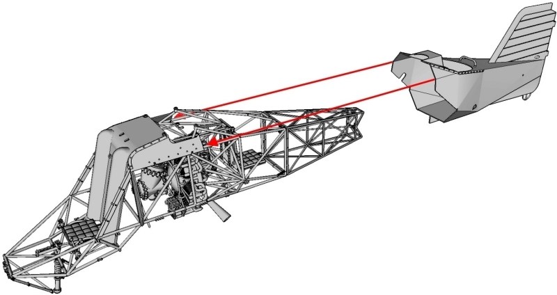
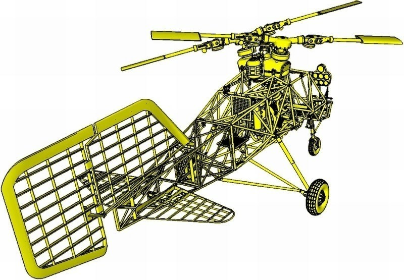
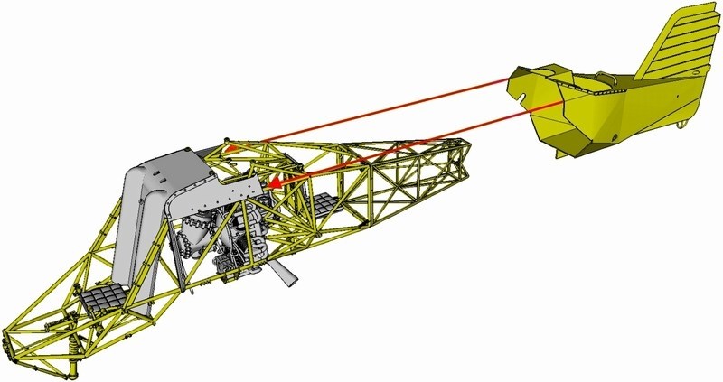
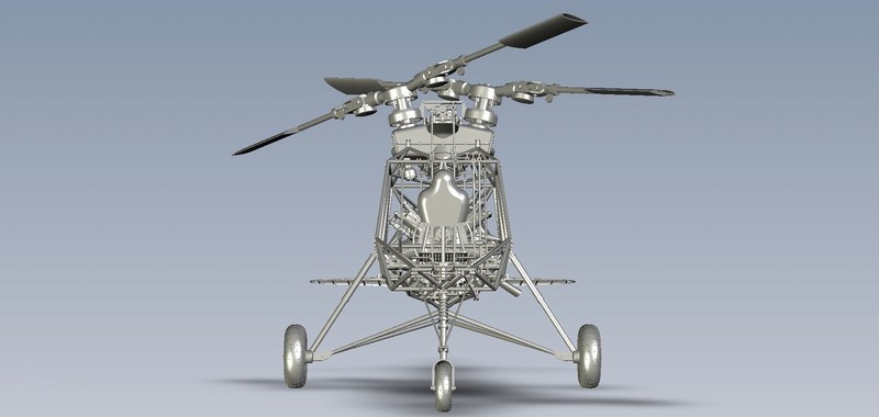
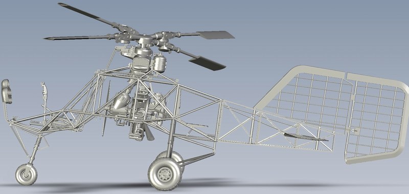
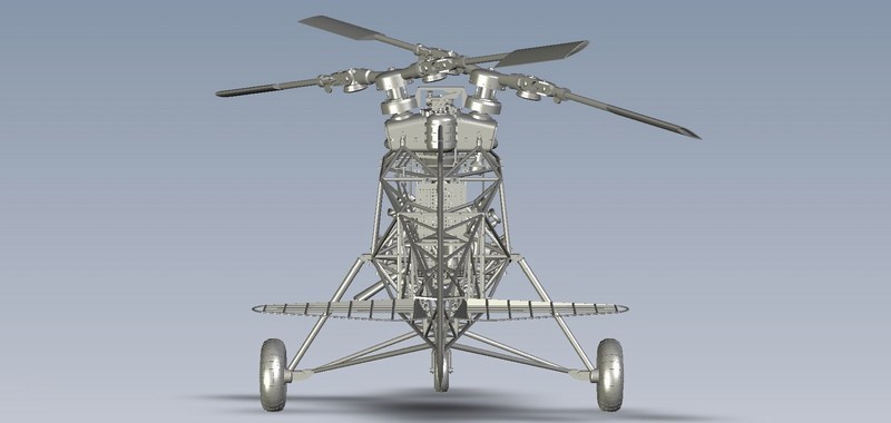
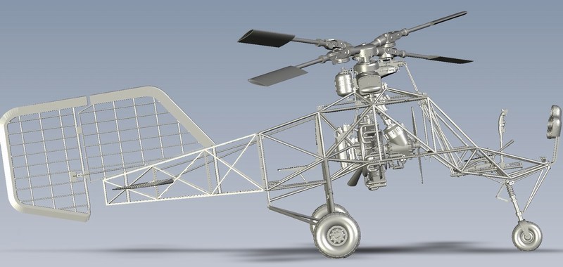
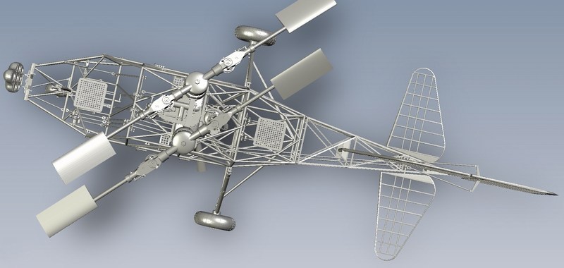
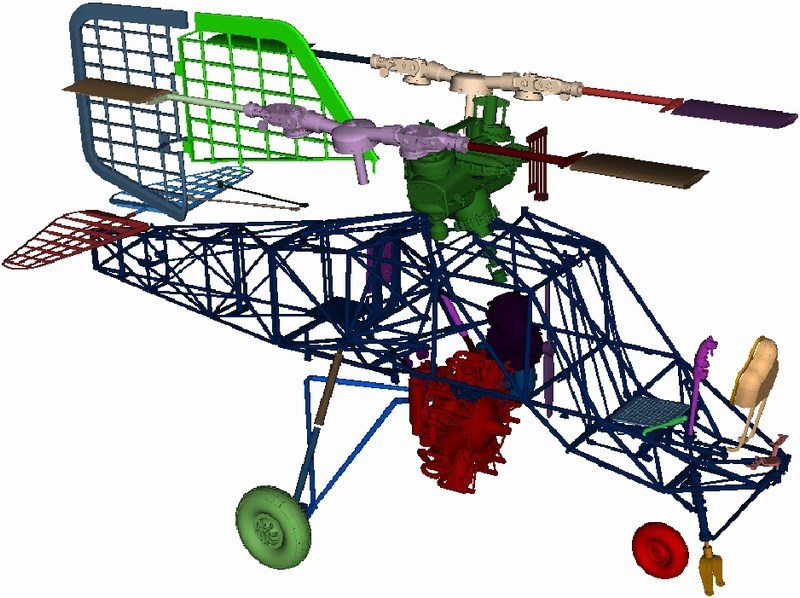
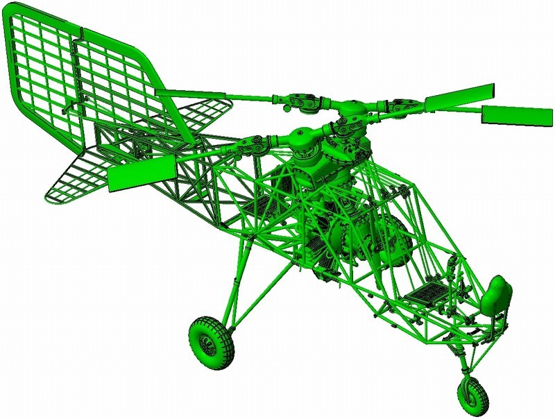
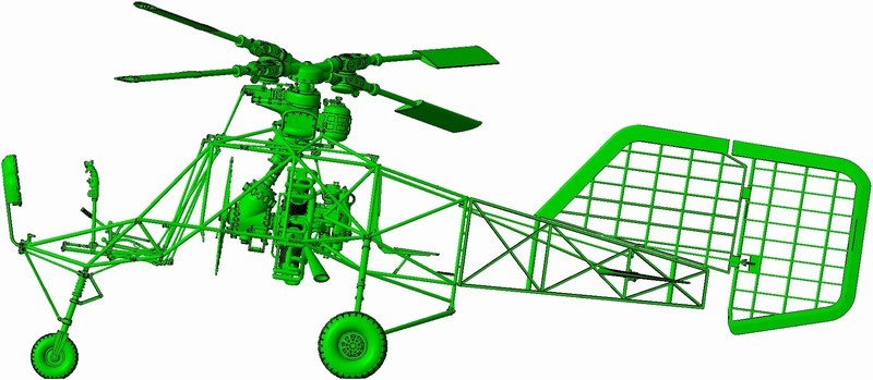
When I started this project almost two years ago, I had in mind to also present the cutaway model kit version step-by-step WIP, as soon as the full fuselage model kit building would have been completed. Actually, both versions already built multiple times as commision work for collectors (for example click HERE to see both versions frames placed side-by-side, while painting process) and I only had to write the text and later attach the pictures shot during assembling & painting process. - 1/18 scale Flettner Fl-282 V21 Kolibri model kit - CUTAWAY version - 1/18 scale Flettner Fl-282 V21 Kolibri model kit - FULL FSG version Considering that over 130+ model kits of both versions sold since Anyuta 3D produced the very first 3D printed V6 version kit under 1/18 scale on early 2014 and due to the fact that the V21 cutaway version became quite popular the last few days, I am now thinking to change a little the basic plan and let the cutaway version step-by-step building edit into the full fuselage version WIP and present them both as a parallel project into a single forum thread.
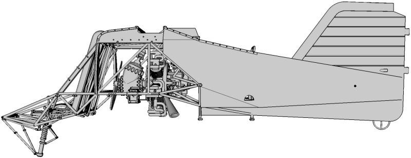
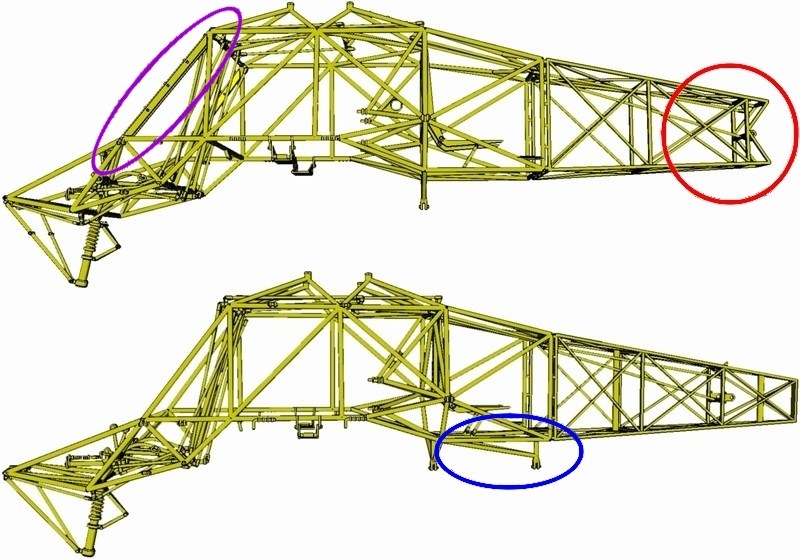
As you all understand, the cutaway version is actually based on the previously released full fuselage model kit, but more than 50% of parts should be CAD designed from the start in order to achieve best results. Although both versions are accurate miniatures of the Kolibri V21 helicopter under 1/18 scale, each one follows different assembling methodology. During the CAD phase, the individual kit parts designed in such way to be as easy as possible for the average modeler to build the model. To do so, the total number of tiny parts reduced (as possible) and different components combined into one part only. IMHO, building something from scratch is not so difficult - after all, we all tried some scratch once in a while. On the other hand, designing a helicopter model from scratch, exploding it into 60+ parts and make each one of them possible to get re-assembled & combined all together in order to create a miniature, is not a piece-of-cake. Speaking of a cutaway, the design difficulty factor gets multiplied. 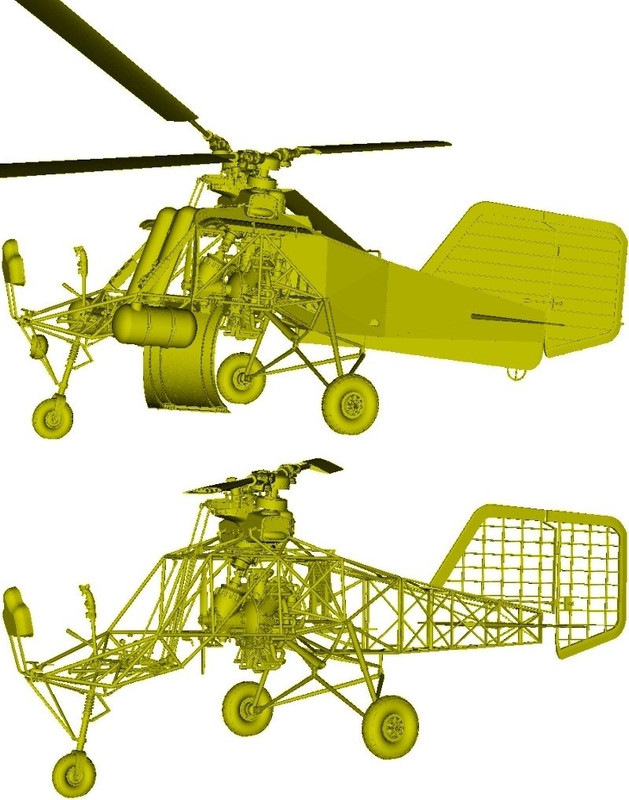 If you download the 102-page "full fuselage" and the 67-page "cutaway" PDF formated building instructions manuals, you'll notice the building process differencies on the first pages. Both versions have exact same dimensions when models fully built, but each assembling process differs a little. For example, as shown into following picture: - The "full fuselage" version kit is equiped with four full-length rotor blades (measuring approx 28 cm long each), but the "cutaway" version has the short / chopped rotor blade parts (marked into red ellipse), to simulate the Kolibri found by British Army and now preserved by Midland Air Museum, in cutaway condition. - The "full fuselage" version's main tubular frame is a little shorter (marked into red circle in following picture) than the normal-length cutaway version's tubular frame. This is because the "full fuselage" version's rear fuselage cover part (which simulates the doped fabric covering over the steel & wooden frame and moreover has the vertical stabilizer attached on) should be dragged along the miniature's wooden frame, until reached down on the transmission pivots. So, as you understand, few milimeters of empty space are needed to ensure the appropriate contact. - The "full fuselage" version's main tubular frame is equiped with a "sleeve" (marked into purple ellipse in following picture) over the front tubular frame. Actually this is a bracket made of wood to support avionics & radio either side of the pilot at cockpit area. This "sleeve" part as well as some others like eg batteries, avionics & radio, 25 litres cylindrical fuel tanks mounted externally on both sides of the pilot, seat cushions etc are also missing from the "cutaway" version. - The undercarriage support (marked into blue ellipse in following picture) is different on each version. Although both versions will show the same on this undercarriage support area when models are buit, the full fuselage version's main tubular frame is missing this part, since it is already attached on the rear fuselage cover part. 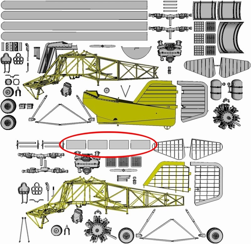
 - The vertical stabilizer of the cutaway version kit is offered as a separate part, which should be glued on the wooden frame. On the other hand, on full fuselage version kit, the vertical stabilizer is already attached on rear fuselage cover and offered as combined items. 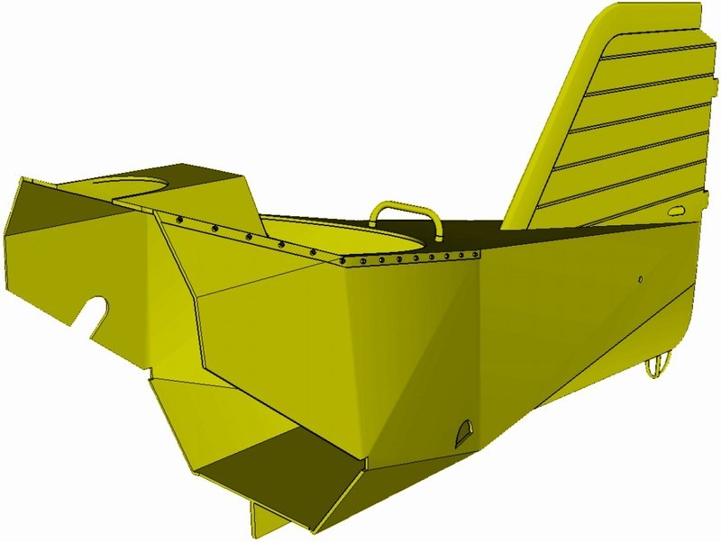
 Düzenleyen Nick_Karatzides - 27/07/2018 Saat 12:37 |
|
|
|
|
|
Nick_Karatzides
Üye
Kayıt Tarihi: 06/06/2009 Aktif Durum: Aktif Değil Gönderilenler: 250 |
Gönderim Zamanı: 18/04/2016 Saat 04:44 |
|
After studing the available reference (few hundreds of pics, blueprints, slides & negatives, videos, technical data and original Luftwaffe's text documents) kindly offered from a variety of sources such as Deutsches museum flugwerft schleißheim, Hubschraubermuseum Bückeburg, Midland air museum, a fellow modeler from Germany whose grandfather was a worker in the Anton Flettner Flugzeugbau GmbH factory at the time when the helicopters manufactured, Mr. Steve Coates author of the "Helicopters of the Third Reich" book and ofcourse Mr. Google (modeler's best friend), the already existing CAD digital file converted to Kolibri cutaway. Now, the model is ready to be forwarded to the 3D replicator and become an actual physical object under 1/18 scale, within short time.
 Düzenleyen Nick_Karatzides - 27/07/2018 Saat 12:37 |
|
|
|
|
|
Nick_Karatzides
Üye
Kayıt Tarihi: 06/06/2009 Aktif Durum: Aktif Değil Gönderilenler: 250 |
Gönderim Zamanı: 18/04/2016 Saat 04:49 |
|
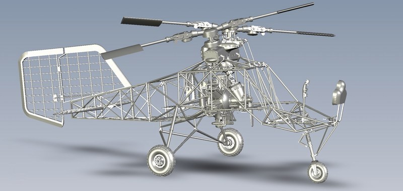
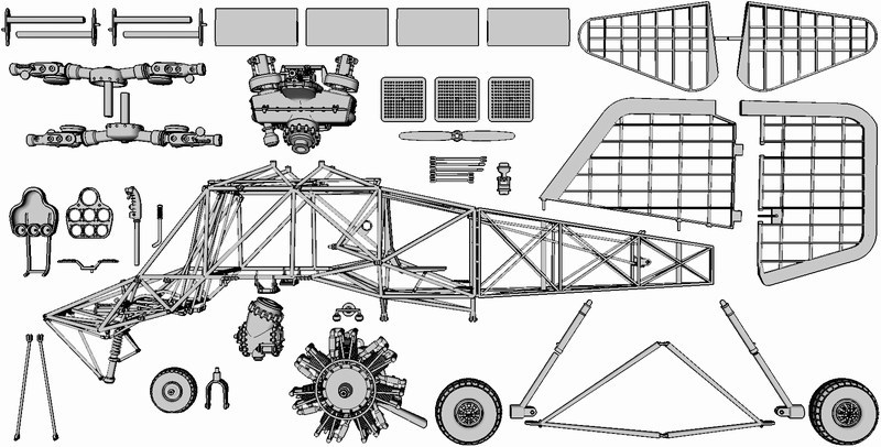
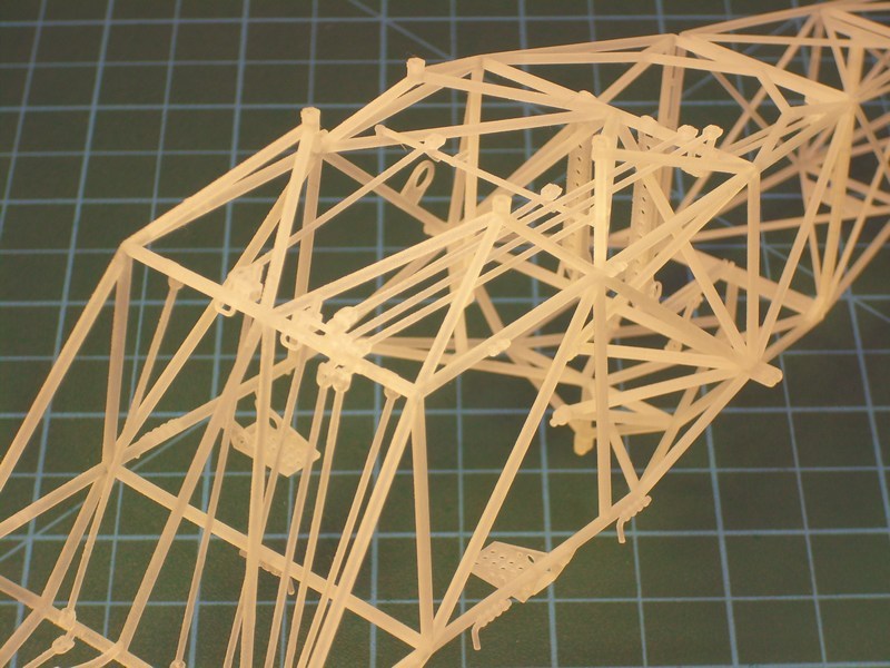
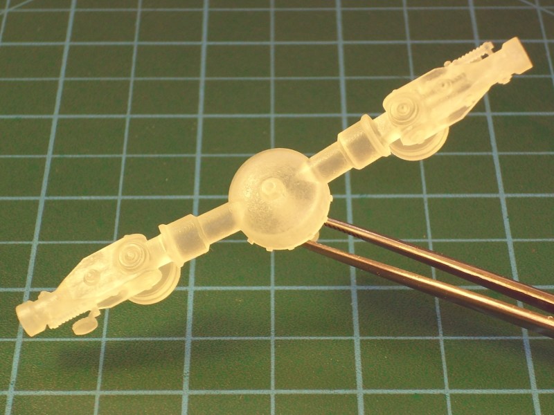
Approx 50% of the components are copied & pasted from the already existing full fuselage version and (lucky me) I did not had to design everything from the start. For example, the complex of intermeshing rotor gearbox, the 7-cylinders radial engine, the 24° angled rotor heads etc. On the other hand, all the wooden frame parts such as the vertical stabilizer, the rudder fin, the horizontial elevator fins and rear fuselage frame details, were CAD designed from the start. Ofcourse, the cutaway version was also built with all included truss-type welded tubes and drive shaft rods with universal joints attached on frame. IMHO, that was mostly preferred because all basic parts should be accurately pre-installed in place without any glue, putty, sanding etc.
 Düzenleyen Nick_Karatzides - 27/07/2018 Saat 12:38 |
|
|
|
|
|
Nick_Karatzides
Üye
Kayıt Tarihi: 06/06/2009 Aktif Durum: Aktif Değil Gönderilenler: 250 |
Gönderim Zamanı: 18/04/2016 Saat 04:57 |
|
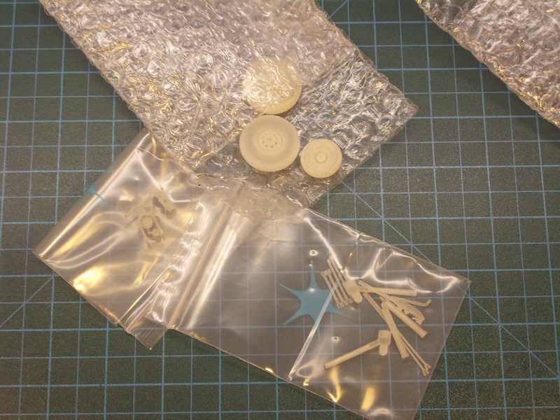
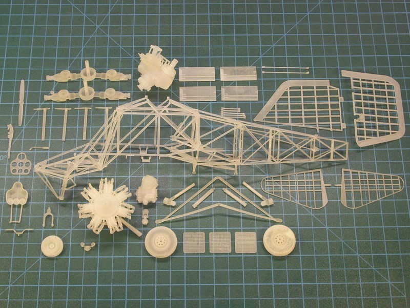
After digitally building the Fl-282 Kolibri cutaway 3D model using only mouse clicks, I saved it as an STL - STereoLithography format binary file and forward it on the 3D replicator to start generating the individual parts of the actual scale model. Once again, I used best available tools & plastic material and asked from Shapeways digital fabrication lab (equipped with a high-precision & high-cost ProJet HD 3000 machine for creating custom made-to-order products), to 3D print it. The 1/18 scale Fl-282 V21 Kolibri cutaway model kit consists of more than 40 different 3D printed parts made of matte translucent plastic material - in fact, the kit parts are quite more, but smaller in size are interconnected on same sprue frame which is counted as one part. Kit was CAD designed and 3D produced in such way to simplify assembling process while maintaining necessary details required by the scale size. Following the instructions described into the 67-page ultra-detailed 1/18 Fl-282 V21 cutaway kit building instructions manual (which can be found HERE as a PDF format downloadable file), the assembling process becomes easy.
 When printing is finished, the model parts are removed from the tray and placed into an oven that melts away the wax support material. Next, the models are placed into an a ultrasonic oil bath to remove any remaining wax residues, and then a ultrasonic water bath to remove any oil on the model. Final inspection and dry by hand follows for every single model part. Although the ProJet HD 3000 prints in high resolution (16 microns per layer) and can easily produce high detailed parts as small as 0.1 mm, it is better to avoid printing such small parts because they could easily get lost while washed into ultrasonic bath later, for wax residues removing. Each complete model kit takes about 5 to 7 days to get produced after order due to increased workload for 3D printed manufacturing demand in Shapeways factory. 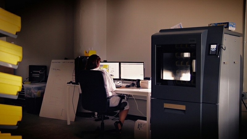
 Düzenleyen Nick_Karatzides - 27/07/2018 Saat 12:38 |
|
|
|
|
|
Nick_Karatzides
Üye
Kayıt Tarihi: 06/06/2009 Aktif Durum: Aktif Değil Gönderilenler: 250 |
Gönderim Zamanı: 18/04/2016 Saat 05:02 |
|
As soon as 3D printing process completed, the produced parts were cleaned & checked for broken parts or imperfections by Shapeways 3D printing lab specialized personnel. Later, everything carefully packed and shipped to my home address using UPS 24hrs delivery service. Once again, I was happy to hold my own custom 3D printed model kit, CAD designed with my laptop and later converted to an actual physical object, under my preferable 1/18 scale.
 Düzenleyen Nick_Karatzides - 27/07/2018 Saat 12:39 |
|
|
|
|
|
Nick_Karatzides
Üye
Kayıt Tarihi: 06/06/2009 Aktif Durum: Aktif Değil Gönderilenler: 250 |
Gönderim Zamanı: 18/04/2016 Saat 05:08 |
|
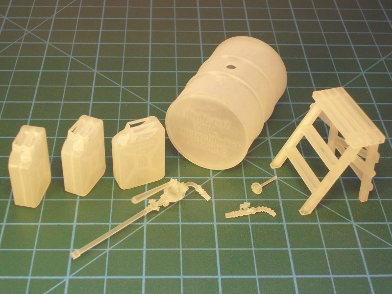
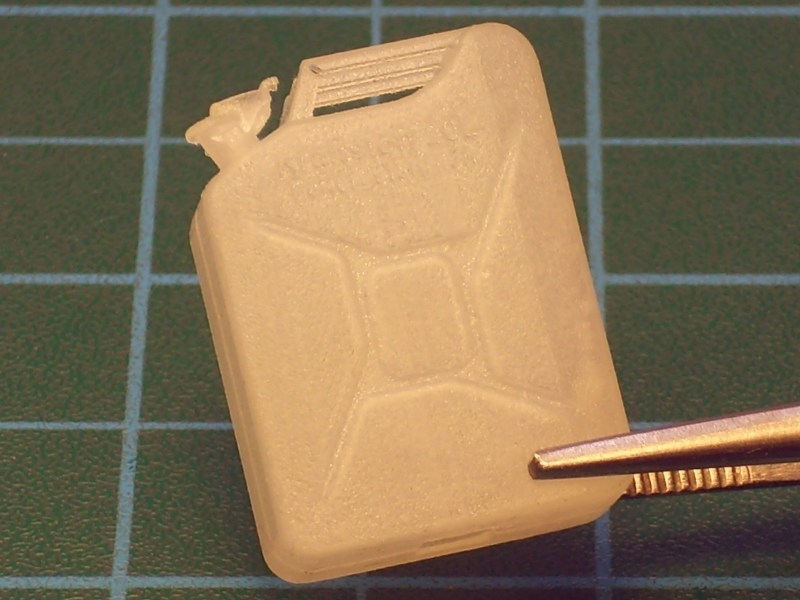
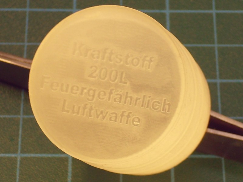
Some additional parts unrelated to the helicopter structure, also 3D printed to be used later as part of a diorama scene. For example few 1/18 scale 20 litres fuel canisters, a couple of 1/18 scale 200 litres fuel drums as used by Wehrmacht, Luftwaffe & Kriegsmarine during WWII with Kraftstoff 200L Feuergefährlich Luftwaffe and Kraftstoff 20 L Feuergefährlich 1941 inscriptions engraved or embossed on side, a 1/18 scale fuel hand pump and one 1/18 scale wooden 3-steps ladder as used by Luftwaffe WWII ground crews and technician personnel for ground vehicle & aircraft maintenance procedures.
 Düzenleyen Nick_Karatzides - 27/07/2018 Saat 12:39 |
|
|
|
|
| << Önceki Sayfa 4 Sonraki >> |
| |
||
Forum Atla |
Kapalı Foruma Yeni Konu Gönderme Kapalı Forumdaki Konulara Cevap Yazma Kapalı Forumda Cevapları Silme Kapalı Forumdaki Cevapları Düzenleme Kapalı Forumda Anket Açma Kapalı Forumda Anketlerde Oy Kullanma |
|
