1/18 scale Flettner Fl-282 V21 Kolibri scratchbuil
Nereden Yazdırıldığı: ModelSitesi
Kategori: Plastik Modeller
Forum Adı: Tayyareler
Forum Tanımlaması: Uçabilen hersey hakkinda bilgi alisverisi alani
URL: www.modelsitesi.com/forum2/forum_posts.asp?TID=8274
Tarih: 02/08/2026 Saat 20:04
Program Versiyonu: Web Wiz Forums 8.04 - http://www.webwizforums.com
Konu: 1/18 scale Flettner Fl-282 V21 Kolibri scratchbuil
Mesajı Yazan: Nick_Karatzides
Konu: 1/18 scale Flettner Fl-282 V21 Kolibri scratchbuil
Mesaj Tarihi: 10/08/2014 Saat 16:56
|
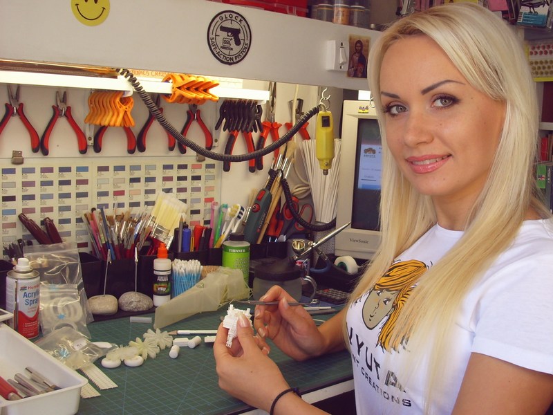
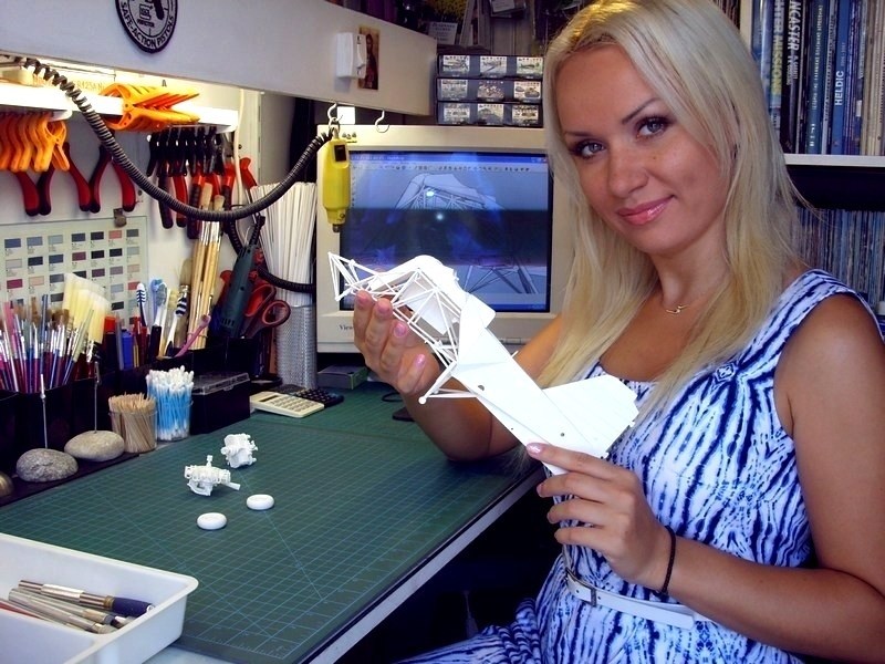
After request, a 1/18 scale Fl-282 V6 helicopter with WWII Kriegsmarine markings built for a wealthy collector from Kiel, Germany. A second Luftwaffes Fl-282 V21 model followed for my own personal collection at home. Since the whole project cost (CAD design, 3D printing & model building) was entirely funded by the client, I did not hesitate to use the best available materials & machines to do the job. The text follows, is to describe the Flettner Fl-282 Kolibri (B-0 series) helicopter as manufactured by Anton Flettner Flugzeugbau GmbH on early 1940ies, used by Kriegsmarine & Luftwaffe during WWII and scratch built by me as a 1/18 scale model, now days. 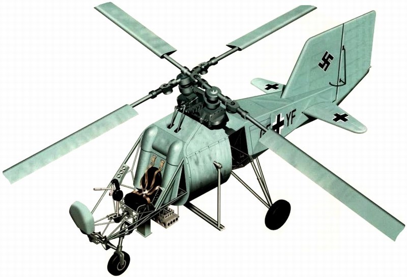
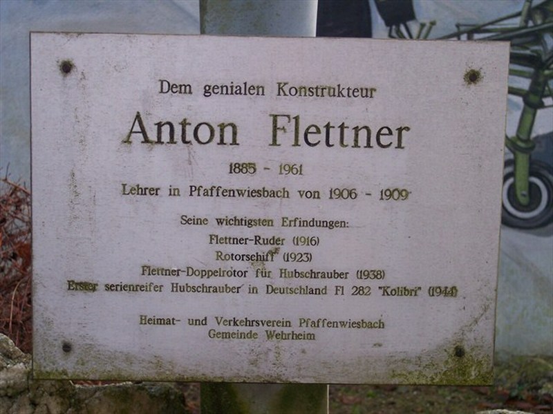
 Anton Flettner was a German aviation engineer & inventor who made important contributions on airplane & helicopter design. During the WWI, Anton Flettner developed remote control & pilotless aircraft projects, which culminated in the prototype Siemens Schuckert Werke 1000 kg wire guided air to surface missile of 1918. Following WWI, he directed aeronautical & hydrodynamic research institute in Amsterdam and during the WWII, he headed the Anton Flettner Flugzeugbau GmbH, which specialized in helicopters. It is believed that the firm was founded in Berlin in 1935. By this time, however, Flettner had developed the idea of counter-rotating, intermeshing twin rotors. Many of his advisers thought that the airflow disturbed by the intermeshing blades would make this system less efficient than one using a single rotor; but Flettner believed that any problems thus encountered would be more than offset by the reduced drag resulting from having no external rotor-carrying structure. His pioneer work is often overshadowed by the more publicised activities of his contemporaries Heinrich Karl Johann Focke and Igor Sikorsky; yet Flettners helicopter, was far superior to the Henrich Fockes FW-61 and made a successful free flight several months before Igor Sikorskys VS-300 began tethered flights. Following pictures taken at Pfaffenwiesbach a district of the municipality Wehrheim, Germany. This artistic wall painting cultural monument, created by the local municipal council in memory of Anton Flettner who was the village teacher in Pfaffenwiesbach from 1906 to 1909. 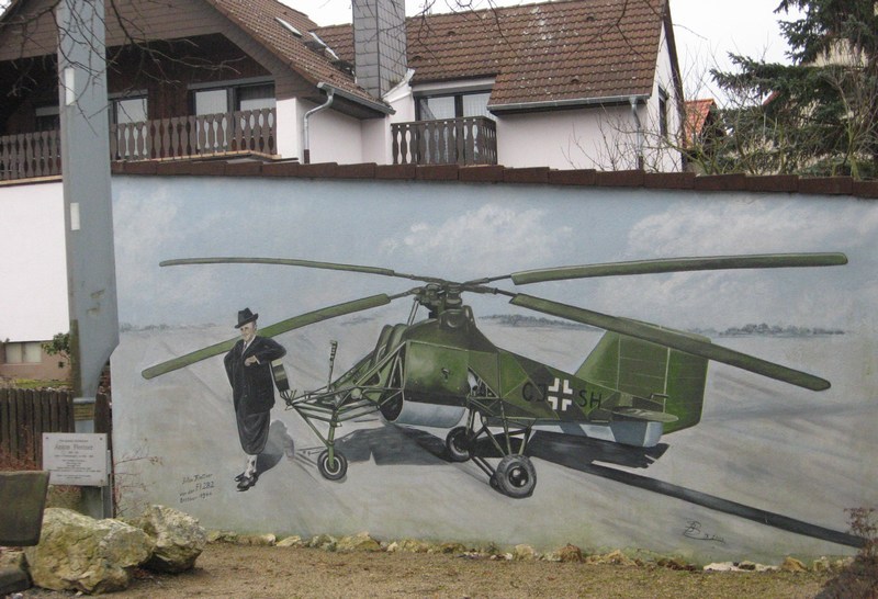
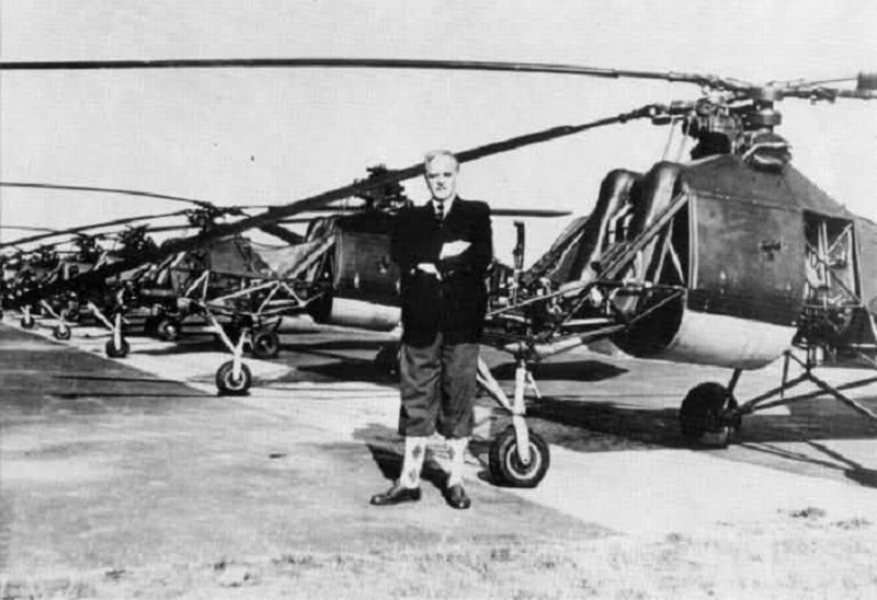
 Although Anton Flettner built his helicopters for the German military, his wife Lydia Freudenberg Flettner was Jewish. Because of his personal friendship relationship with head of Gestapo, Heinrich Himmler, Anton Flettners Jewish wife and their family safely moved to Sweden for the duration of World War II. Anton Flettners partner and confidant was Dr. Kurt Hohenemser, a brilliant and thorough engineer who developed the details necessary for the helicopters success. Dr. Hohenemser's father was also Jewish, yet the pair remained unharmed during their tenure together throughout the War as they worked to develop the helicopter for military use. While the final product could be factory assembled, Anton Flettner and his partner Dr. Kurt Hohenemser insisted that they were the only ones who were capable of assembling the complex intermeshing rotor gearbox assembly. However, plans for 1000 helicopters mass production were made, the project was disrupted by the destruction of the designated factory by Allied bombing. 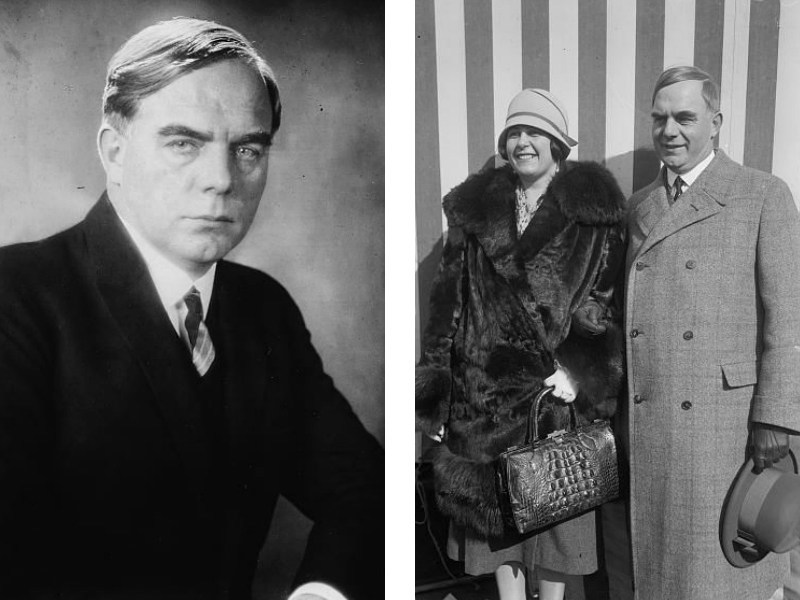 In following pictures, Anton Flettner is proudly posing in front of his Fl-282s fleet at Schweidnitz (today Świdnica, Poland), on October 1944. The first helicopter is a V14 registered as CJ-SH. 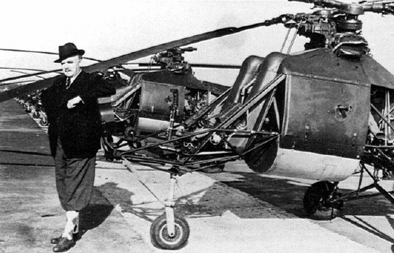
 Upon the WWII conclusion, Anton Flettner was held in the Dustbin interrogation camp at Kransberg castle. After 1945, Flettner, along with many other aviation pioneers, was brought to the United States as part of Operation Paperclip. He started Flettner Aircraft Corporation, which developed helicopters for the US military. His company was not commercially successful, but his work was shared with the Army Air Corps. Many of his designs, such as intermeshing rotor concept, saw widespread use in a series of postwar helicopters built by Kaman for the US Navy and USAF. Anton Flettner moved to the United States in 1947 to work as a consultant to the Office of Naval research and became the chief designer of Kaman Aircraft, creating the Kaman HH-43 Huskie, a concept with intermeshing rotors. He died at age 76 in New York City, USA on December 29th, 1961 and buried in Eddersheim cemetery at Frankfurt, Germany where he was born. In following photograph, Anton Flettner (2nd from left) meets Wernher von Braun (3rd from left). 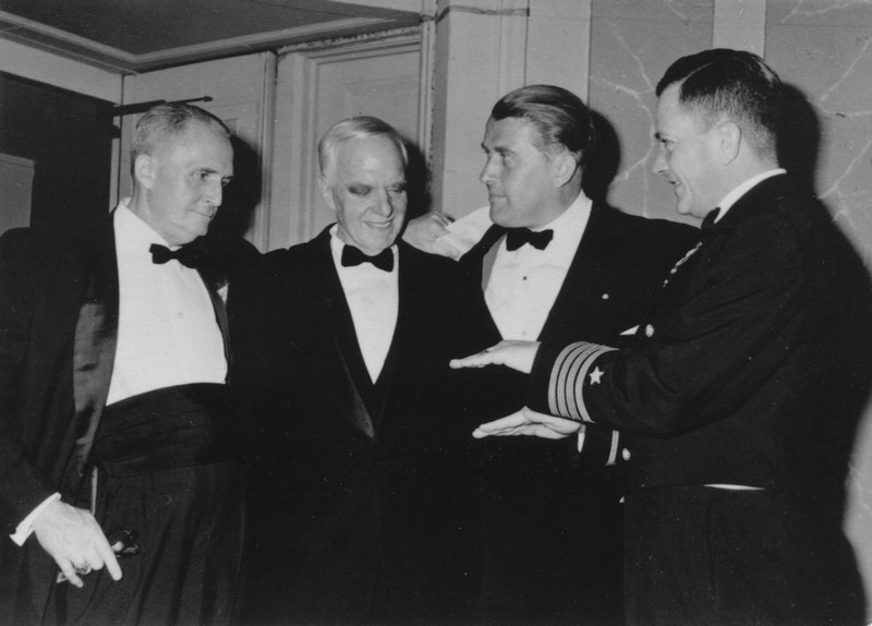 |
Cevaplar:
Mesajı Yazan: Nick_Karatzides
Mesaj Tarihi: 10/08/2014 Saat 17:52
|
The Flettner Fl-282 Kolibri, a single seat open cockpit intermeshing rotor synchropter, was the Worlds first mass produced helicopter and the first helicopter to land on a ship. Today one can say without exaggeration that it was the best helicopter of its day. It was actually an improved version of the previously built Flettner Fl-265, a pioneering example of a synchropter with two intermeshing rotors. The exact date on which the RLM issued the development contract for the Fl-282 is not really known. It can be assumed with certainty, however, that design work was begun in 1939 while testing of the Fl-265 was under way. All the test results and experience from the previously built Fl-265 were applied to the design of the Fl-282. By mid-August 1941 work on the Fl 282 V1 had progressed to the point where it could be used on the ground as a transmission unit test bed. The test bed was anchored but could climb the length of the restraint to a certain height and hover. 125 hours and 39 minutes were spent in these tests, which lasted until November 21st 1941. In the event of the destruction of the V1 or a lengthy interruption of testing due to some other problem, it was planned to use the V4 as a replacement test bed. First free flight was made by the V2 on October 30th 1941. At the controls was test pilot Ludwig Hoffmann, who had joined Flettner as the successor to company pilot Perlia. Flight tests resumed in March 1942 following design changes to the cardan shaft; the tests revealed a significant improvement in the helicopters handling. The Fl-282 V2 was taken out of service on May 25th 1942; the aircraft's transmission & engine were removed for use in other prototypes. Test pilot Ludwig Hoffmann carried out two altitude flights in the Fl-282 V3 on April 27th 1942. On the first he reached a height of 3500 meters over the takeoff point and on the second attempt 3800 meters in 36 minutes (from 15:17 to 16:10 hours). In following pictures, the Fl-282 prototype helicopters. The V2 (registered as GF-YB) with fully glazed cockpit, completed its first flight on October 30th 1941 and the V3 (registered as GF-YC) had H shaped horizontal stabilizers with end plates. The first three prototypes (A series) had fully enclosed cabins made up of a series of optically flat plexiglass panels, faired-in rotor pylons and well-contoured fuselages. The V3 version was fitted with endplate auxiliary fins and a long underfin beneath the rear fuselage. Later machines had more utilitarian bodies. Some (B-0 series) had a completely open pilot's seat, some (B-1 series) had semi-enclosed cockpits by flat plexiglass panels and finally some others (B-2 series) had cockpits enclosed by combination of plexiglass & wooden sidewalls. 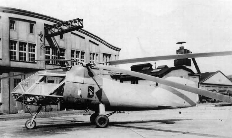
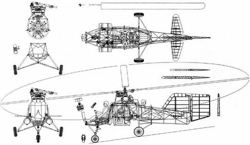
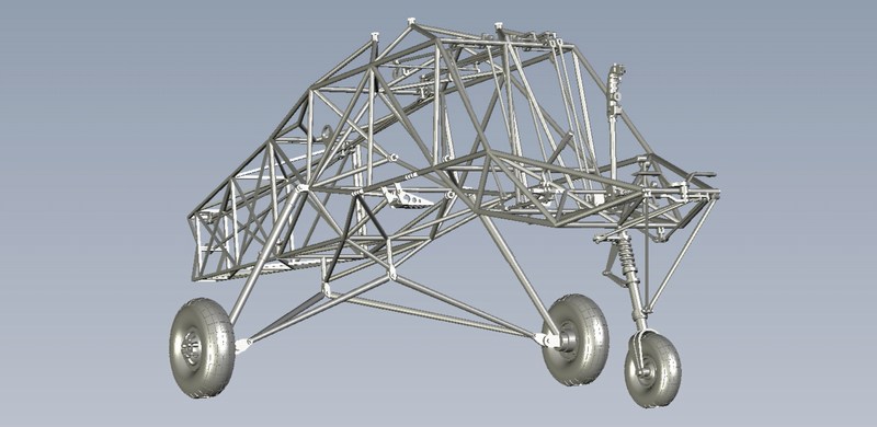
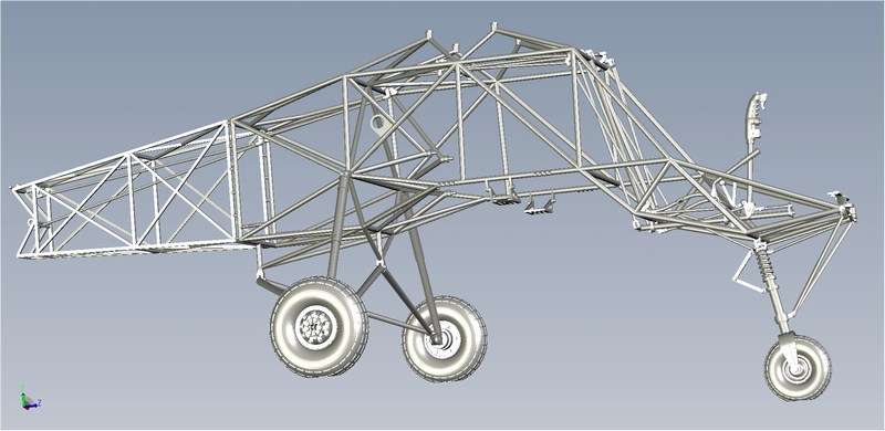
 The idea of the helicopter was new at that time and Anton Flettner and his team made a lot of efforts to convince the German Air Ministry that its a good product. One of these efforts was to take an average German housewife and teach her to fly the new helicopter. As seen into following photograph, they finally proved that the vehicle was extremely stable and very easy to fly. So easy, that an average German housewife with no previous flying experience, managed to control the Fl-282 V22 (registered as CI-TV) helicopter, after only 3 hours of flight training. 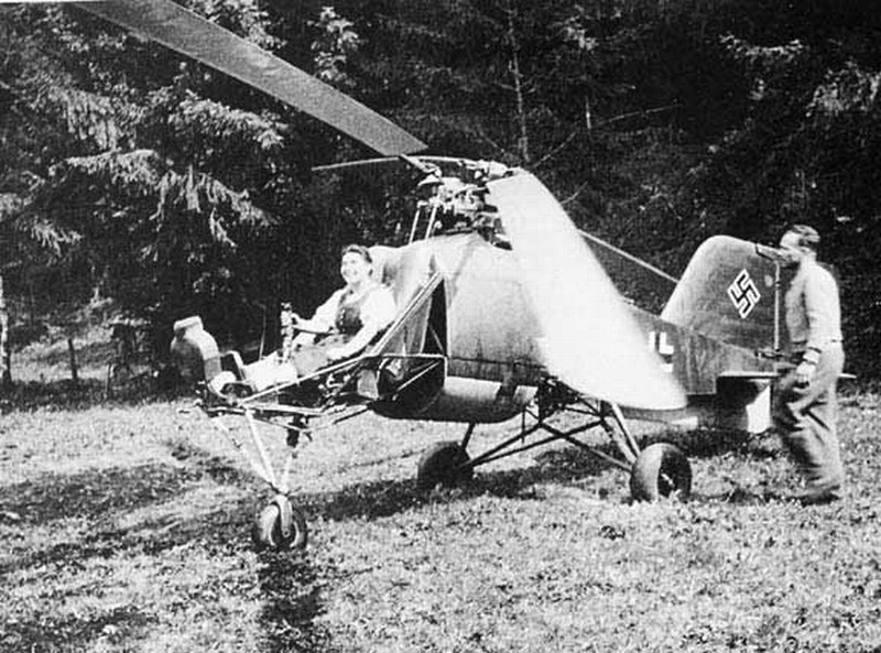 The fuselage was constructed from truss-type welded steel tube, covered with doped fabric. It was fitted with a fixed non-retractable tricycle type undercarriage, with the braced fixed nose wheel with VDM oil shock absorber leg coupled with the rudder foot pedals for steering. Nose wheel was equipped with a 350x150 mm tire and main gear with 465x165 mm tires. The rectangular outline with rounded tips rotor blades were made by tubular steel spar with riveted-on wooden ribs and plywood skin with fabric covering and axes of both rotors were angled outboard at 12° from the vertical. Seen from above, the right rotor rotates clockwise and the left rotor counter clockwise. At the rear end of the fuselage, a two-part horizontal stabilizer with single spar was provided for trimming purposes and a rudder fin of very generous area. This large area was necessary because much of it was ineffective due to the poor aerodynamic shape of the fuselage causing rearwards flow separation and turbulence. It was constructed by tubular steel spar with riveted-on wooden ribs, plywood leading edge & fabric-covered. Steering of the Fl-282 was by a combination of the rudder and differential collective pitch change on the two rotors, but only the rudder could give steering during autorotation since collective pitch was then ineffective (another reason for the large rudder area). Rudder fin was made of wood and covered by fabric, with 40° deflection. The vertical stabilizer and the elevators were also made of wood, with plywood leading edge and fabric covering, bolted to fuselage frame. 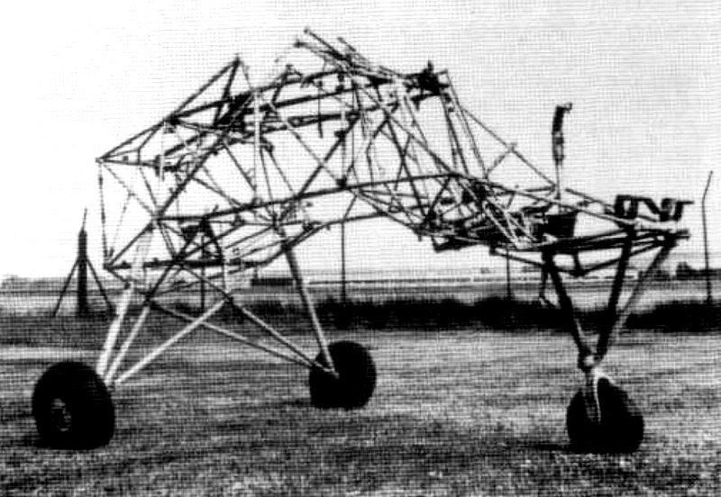
 |
Mesajı Yazan: Nick_Karatzides
Mesaj Tarihi: 10/08/2014 Saat 18:05
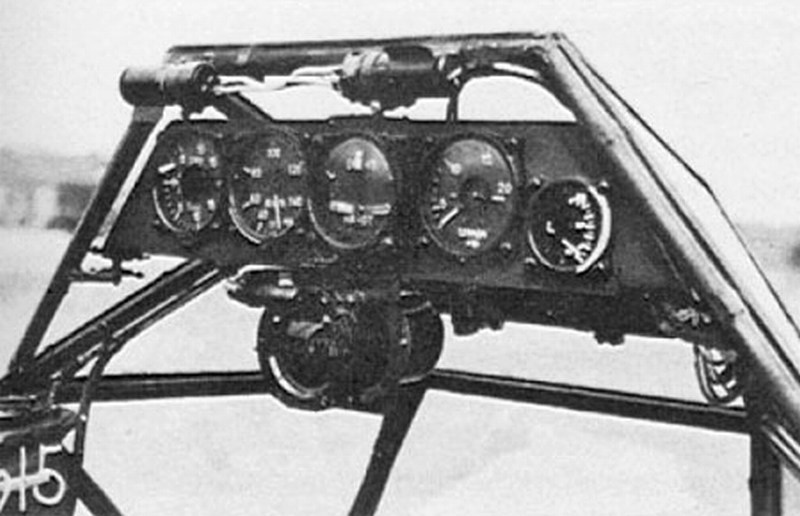
It was equipped with flight and navigation instruments such as an ASI - AirSpeed Indicator, an altimeter, a VSI - Vertical Speed Indicator, a turn & bank indicator, RPM indicator for rotors, rotor blade angle indicator, a master compass and a dashboard clock. Radio & signalling equipment consisted of a FuG 19 ultra short wave radio installation. Back type parachute, first aid kit, signal flare pistol and one-man inflatable raft were also present. In following pictures, the instrument panel of the first three prototype helicopters with fully enclosed cabins made up of a series of optically flat plexiglass panels.
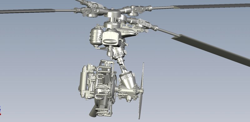
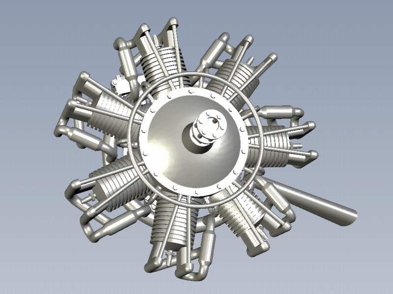
 The Flettner Fl-282 Kolibri was equipped with a Bramo Siemens Halske SH-14A, 7-cylinders radial engine of 119 kW (160 hp) mounted in the center of the fuselage, with a transmission unit on the front of the engine from which a drive shaft ran to an upper gearbox, which then split the power to a pair of opposite drive shafts to turn the rotors. The SH-14A was an already tried engine design that only required servicing every 400 operating hours. 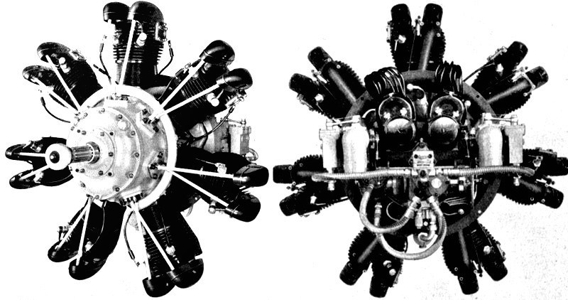
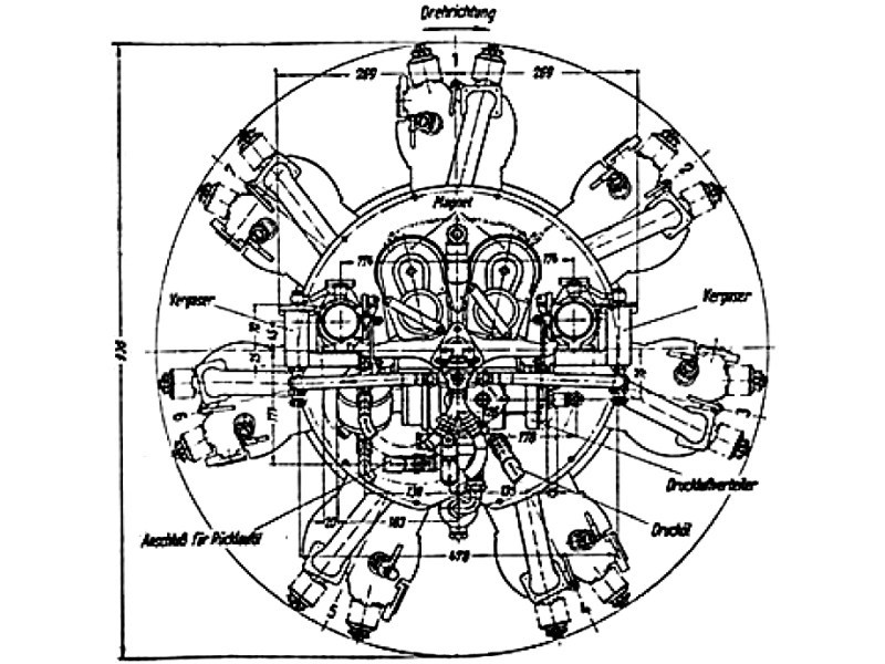
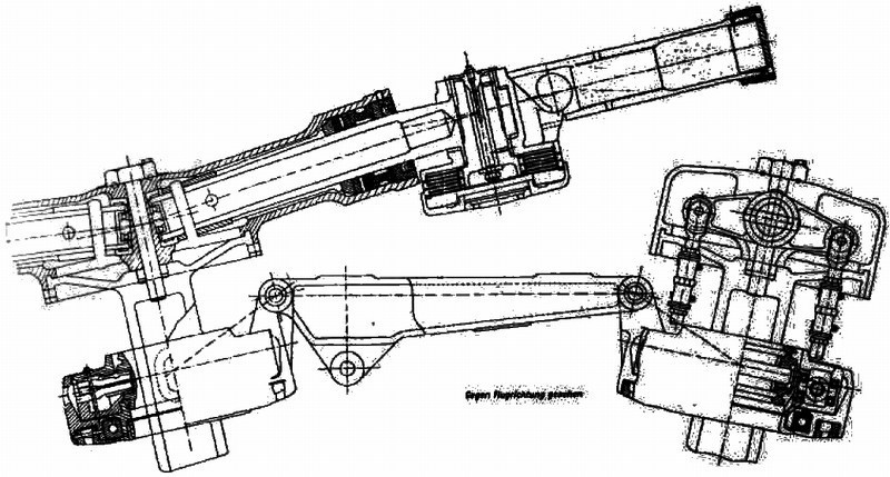
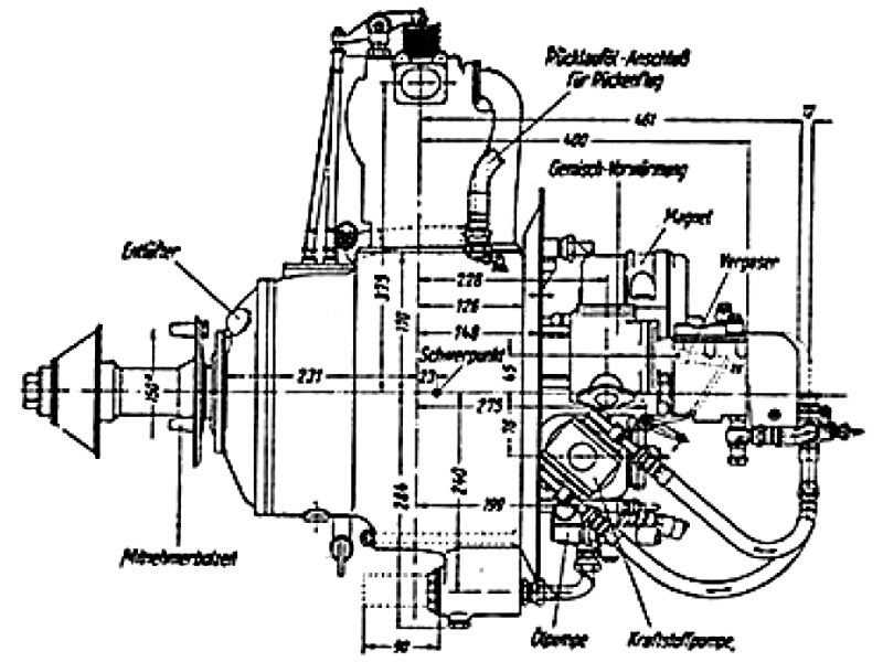 A drive shaft with universal joints took the drive from the engine transmission unit to the upper transmission unit, which consisted of gears and shafts connecting the two rotor shafts. The final cross-shaft between the two rotor shafts was fitted with a free wheeling unit to disconnect the engine drive, and also with a rotor brake. On the drive-shaft from the engine, a friction disc clutch was fitted which was used for running up the rotors until there was no slippage, when a positive dog-type clutch, on the same shaft, was then engaged. Total reduction through all the transmission units was 12.2 to 1. Cooling air for the enclosed engine was drawn in through openings beneath the fuselage by an eight blade wooden cooling fan with direct drive from the engine and a high pressure air tank was connected to the engine cylinders through a distributor for starting. 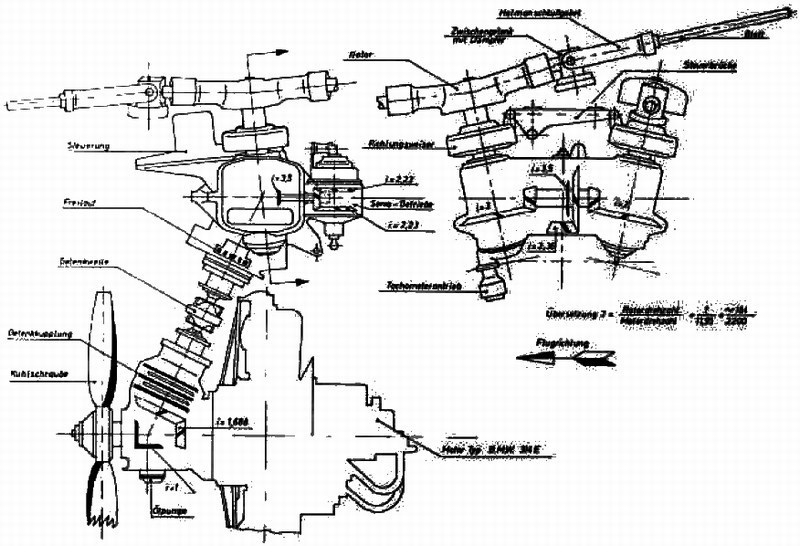 |
Mesajı Yazan: Nick_Karatzides
Mesaj Tarihi: 10/08/2014 Saat 18:21
The two 2-blade rotors, which were synchronized to be parallel in the 45° position, were mounted on shafts having an included angle of 24° between them and an inclination forward of 6°. The rotor blades consisted of wooden ribs mounted on tubular steel spars with a covering of plywood followed by fabric. Flapping and dragging hinges were fitted, the latter having friction dampers. A centrifugally operated blade pitch governor held the rotor rpm within prescribed limits, the governor being driven through clutches from the rotor transmission. In order to ensure that power-off autorotation was not lost, the governor was set for a minimum rotor speed of 160 rpm. With the use of his collective pitch lever, the pilot could over ride the governor but only to increase rpm. Under certain conditions, self-excited oscillations could occur in the rotor; this happened in flight on one occasion when an Fl-282 was being flown with a high collective pitch and the low rotor speed of 140 rpm (compared with the recommended 175 rpm). Vibration became so severe that the pilot prepared to bail out, but, before he could do so, the machine went into autorotation and the vibration ceased.
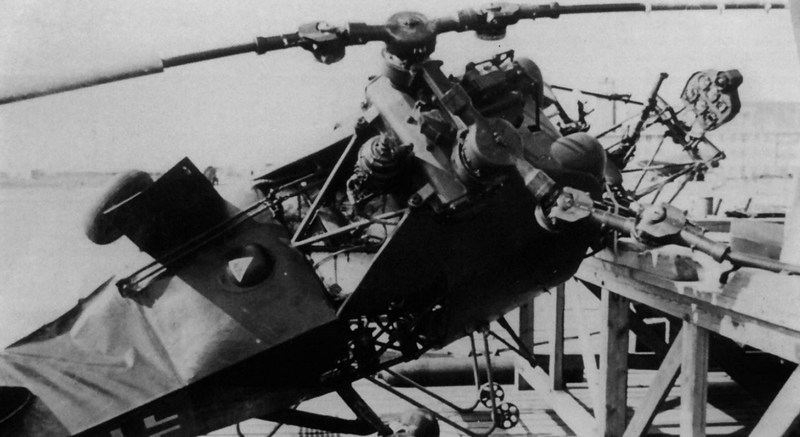
 The Fl-282 was more highly developed and flew more hours than any other German helicopter, and very extensive tests and measurements were made of all flight aspects. Most of this test work was done by Anton Flettner's chief pilot Oberleutnant (Luftwaffe 1st Lieutenant) Hans E. Fuisting, who also undertook blind flying and trained many of the 50 pilots who learned to fly the Fl-282 Kolibri. Other test pilots participated test pilot FliegerStabsingenieur (Luftwaffe Major) Gerhard Geike, Dipl. Ins. Hans Fischer and Dipl. Ins. C. Bode. Some new pilots ran into trouble when flying near the ground, because, as they turned with the wind, they lost lift and struck the ground. One new pilot had a fatal accident when flying his Fl-282 blind in cloud, and the assumed cause of the accident was that the machine had been dived and the controls then pulled back so violently that the blades were forced into each other or into the tail. The diving speed thereafter was restricted to 175 km/h. On occasions, the Kolibri was landed autogyro way and without the use of collective pitch. This was done by vertically descending, diving nose-down and then pulling back on the controls to land. Unfortunately, by using this landing technique without the use of collective pitch, on (at least) one occasion, the tail boom hit the ground and was damaged. As seen into following two photographs, the CJ-SK registered Fl-282 V17 helicopter, following a crash-landing at Travemünde, on April 13rd 1944, with test pilot FliegerStabsingenieur (Luftwaffe Major) Gerhard Geike behind controls who replaced the main test pilot Fliegerstabsingenieur Dipl. Ins. Hans Fischer after he was badly hurt in a Dornier Do-217 crash. 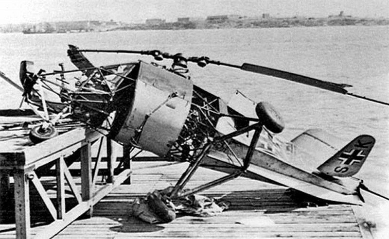
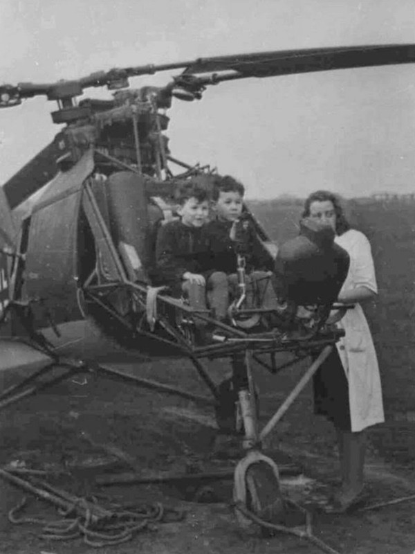
 Extremely manoeuvrable and very stable, even in gusty conditions, the machine could be flown hands-off in forward flight above 60 km/h for indefinite periods by making an adjustment to neutralize the loads on the controls. However, in forward flight at speeds below 60 km/h there was some longitudinal instability, which reached a maximum at about 40km/h. Another slight criticism of the Fl-282 was that it vibrated rather badly while the rotor was running up on the ground, but this vibration decreased upon lifting off, although there was still a certain amount of vibration transmitted to the control column, which was sluggish and tended to overshoot the requisite amount of movement. Although many of the mechanical components were unnecessarily complicated and heavy, the general design and workmanship were of excellent quality. Since taxiing under its own power was strictly forbidden, the Fl-282 V12 registered as CJ-SF seen in following picture, pushed back by ground personnel. This rule imposed because the non vertical angled rotor hubs resulted in the blade tips at the sides of the craft being around human body height and made the craft dangerous to approach from the ground whilst the blades were spinning. In addition, the blades could be damage by contact with the ground. At heliports these two problems could be overcome, but at unprotected sites this would be a concern. So, they had a simple rule that ground crew could not approach at that time or only directly from the front. 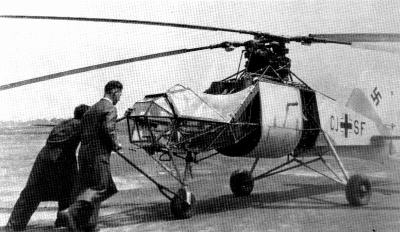 In following picture, Emil Arnolt (left) chief designer at Anton Flettner Flugzeugbau GmbH, test pilot Oberleutnant (Luftwaffe 1st Lieutenant) Hans E. Fuisting and a mechanic (name unknown), in front of companys factory plant. Next photograph, Emil Arnolts family (wife & kids) having their first contact with the new helicopter. Pictures provided by Carsten Arnolt, grandson of Emil Arnolt. 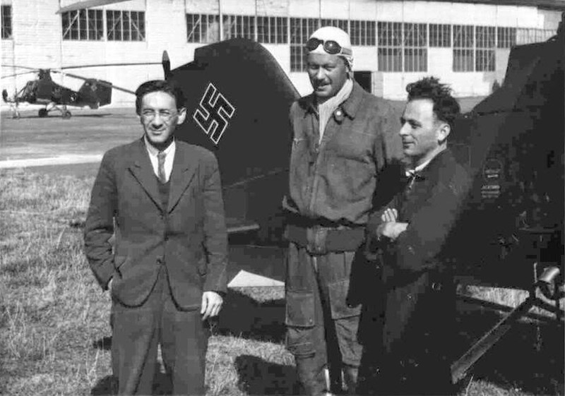
 |
Mesajı Yazan: Nick_Karatzides
Mesaj Tarihi: 10/08/2014 Saat 18:43
The Kriegsmarine HQs was impressed with the Flettner Fl-282 Kolibri and wanted to evaluate it for submarine spotting duties, ordering an initial 15 helicopters, to be followed by 30 production models. Flight testing of the first two prototypes (with enclosed plexiglass panelled cabins and 3-bladed rotors installed, instead of the 2-bladed rotors on production models) was carried out through 1941, including repeated takeoffs and landings from a 13 m² wide platform pad mounted on the German cruiser Köln. Intended roles of Flettner Fl-282 Kolibri included ferrying items between Kriegsmarine ships and naval reconnaissance operation from cruisers and other warships. The entire Fl-282 flight test program was not conducted at Rechlin, as was customary for land based aircraft; instead, from August 1942, trials were carried out at E-Stelle See Travemünde. Travemünde was selected because the air traffic safety ship Greif was based there and could be used for deck landing trials. The site also simplified helicopter sea trials with the navy, it was also imperative to move the site of the trials from Flettner's facility in Berlin, where there was a greater risk from the growing Allied bombing raids.
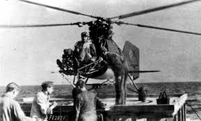
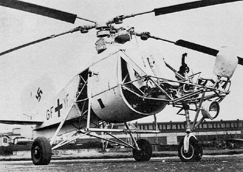
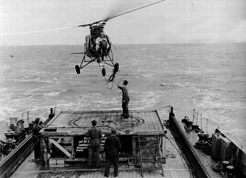 On September 1942 a Fl-282 Kolibri V12 version with registration CJ-SF, was initially tested by Anton Flettner's chief pilot Oberleutnant (Luftwaffe 1st Lieutenant) Hans E. Fuisting, aboard the Kriegsmarine's ship Greif', a 2000 ton aircraft salvage ship. Few weeks later, in October 1942, another two Fl-282 helicopters, one V6 version with registration GF-YF and one V10 version with CJ-SD registration, were delivered to Trieste with their personnel, including Hauptmann (Luftwaffe Captain) Klaus von Winterfeldt, Anton Flettners chief pilot Oberleutnant (Luftwaffe 1st Lieutenant) Hans E. Fuisting and a 3rd pilot (his name & rank are unknown) plus three mechanics for technical support. From November 1942 until February 1943, the Fl-282 V6 registered as GF-YF, had been extensively tested aboard the Kriegsmarine's minelayer Drach (Schiff 50, ex-Yugoslavian Zmaj) while operating in Aegean Sea, north of Crete, Greece, following the absence of RAF aircrafts in the area for few months. The second V10 Kolibri registered as CJ-SD, was a reserve machine that stayed ashore. The helicopter was operated from a 15 m² wide platform pad, while the ship was moving. It was no simple matter setting a helicopter down on the waving deck of a ship, so a special system was designed to bring the two vehicles together. A 10 meters long cable was attached to a swiveling fixture on the bottom of the helicopter. The pilot would bring the helicopter in to hover just out of ground effect over the platform and release the free end of the cable. Two men on the deck would grab the cable and hook it onto the winch drum, pulling the helicopter down to the deck. While this was going on the pilot applied enough power to keep the cable taunt, thus the helicopter took the waves in unison with the ship. The reverse procedure would be performed for take-off. A similar method is still used today for operating helicopters off of ships in rough weather. 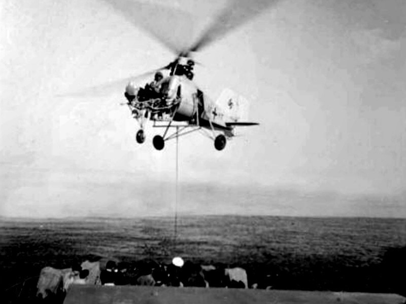 By 1943, the Fl-282s were routinely being used by the Kriegsmarine for convoy protection and reconnaissance. Usually they flew from platforms above the gun turrets of convoy escort vessels in the Aegean, Baltic and Mediterranean Seas, often in extreme weather conditions. The Flettner Fl-282s revealed control & performance qualities well above expectations and found to be especially valuable at dawn or dusk when fixed wing aircraft pilots did not have good visual contact in the poor light. As an important area of operations, the Mediterranean Sea offered the promise of worthwhile missions for the Kolibri and the tactical trials could be conducted into the most favourable weather conditions. As well, the U-617 submarine was also available to participate to the trials. During the day, helicopter crews could spot the submarine as deep as 130 ft. Once a sub was spotted the Kolibri could easily match the speed & course of the submarine, which was impossible for the fixed wing aircraft with stall speeds higher than the cruise speed of a submarine. The Fl-282 would then radio transmit the sub's position to the convoy and if a warship was dispatched to attack on sub, the helicopter would mark the target's position with a magnesium flash bomb or marker flares. The V9 helicopter registered as CJ-SC was the prototype for a version to be operated by the Navy from large submarines and designated as Fl-282 U (Umbau) Modified Model in Form of a Standing Cylinder version. Although the Fl-282 was designed so the rotor blades and landing gear could be removed and the helicopter stored in a compact area such as the pressure tank of a U-boat, there is no evidence that it was ever used this way. 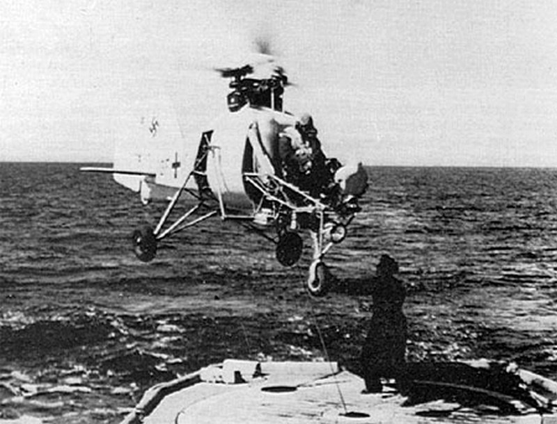 Further service trials carried out later in the Baltic Sea aboard the anti-submarine vessel KUJ 13 (type KUJ 41) from 24th April 1943 to 15th May 1943, in conjunction with the 21st U-boat training flotilla, as part of the Kriegsmarines ongoing exercises for sea missions in the area of Danzig Bay and the north tip of Gotland island. The fleet exercises involved underwater attacks on simulated convoys consisting of target vessels & escorts. Once, over a convoy, test pilot Hauptmann (Luftwaffe Captain) Klaus von Winterfeldt was able to make out all twelve (!!!) submarines that sent against convoy. 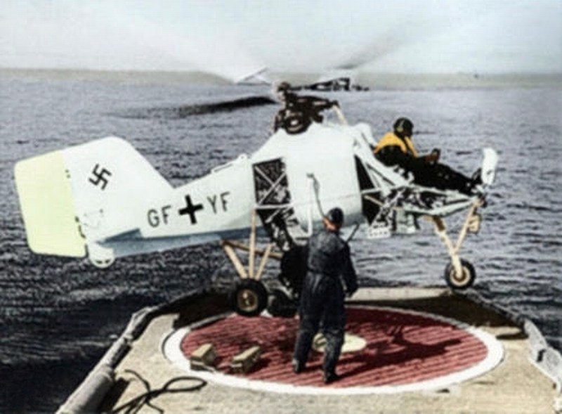 On May 3rd and 4th 1943, a special experiment took place in cooperation with the DVL's Institute for Marine Aviation. It involved towing tests with a 50 kg gliding body. The proposal originated from Hauptmann (Luftwaffe Captain) Klaus von Winterfeldt, director of the Erprobungs und Lehrkommando (Testing and Instruction Detachment) that time, who carried out the towing flights from an anti-submarine vessel in Gotenhafen. In addition to its role as a reconnaissance aircraft in support of the sub-chasers, armed with bombs the Fl-282 was also to participate actively in the anti-submarine role. Unfortunately, on May 10th 1943, Hauptmann (Luftwaffe Captain) Klaus von Winterfeldt (pictured in following photograph) run out of fuel, crashed in sea (35 nm NE from Christlansoya island) and killed, while flown the GF-YF registered V6 testing helicopter. He was posthumously promoted to Luftwaffe Major for his work in helicopter development. 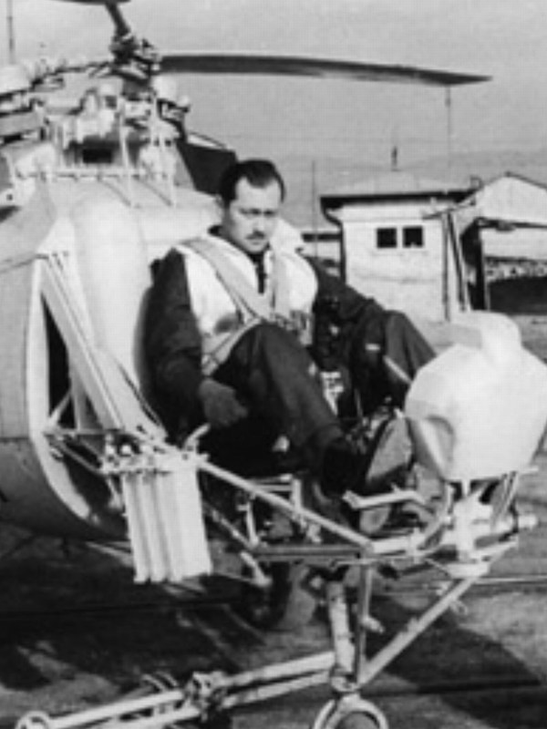 |
Mesajı Yazan: Nick_Karatzides
Mesaj Tarihi: 10/08/2014 Saat 18:53
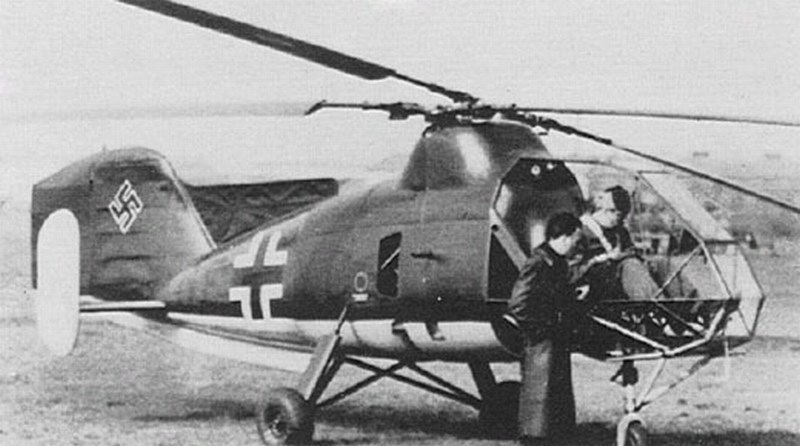
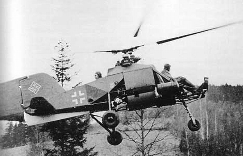
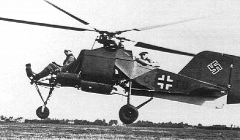
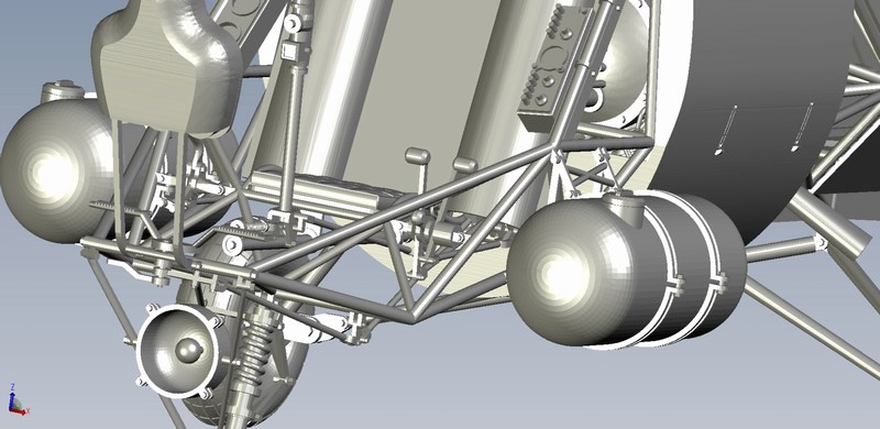
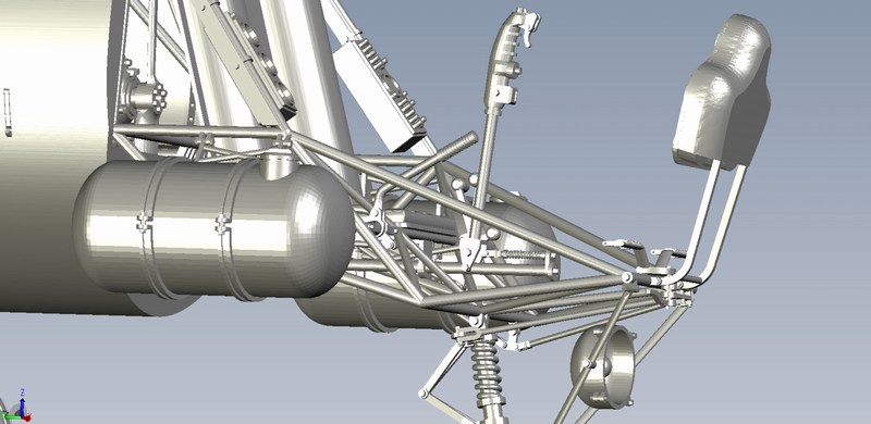
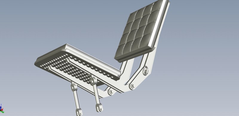
However, as the War progressed, the Luftwaffe began considering converting the Kolibri for battlefield use. Until this time the helicopter had been flown by a single pilot, but by then a seat for an observer was added at the very rear of the craft, resulting in the V21 and later the V23 reconnaissance liaison versions with two seats for pilot and observer. These helicopters later proved a useful tool on multiple roles, used for picking up downed airmen, artillery spotting and other observation duties. It was similar to the naval helicopter, but a rearwards facing seat for the observer was positioned behind the rotor shafts. This made necessary the removal of the main fuselage fuel tank with consumable content 105 litres of 87-octane aviation gasoline. The standard fuel tank was removed and replaced by two un-protected, 25 litres cylindrical fuel tanks mounted externally on both sides of the pilot seat. The FuG 19 ultra short wave radio installation of the naval version was also replaced with a smaller and lighter short range radio. The naval versions one-man inflatable raft, the single-barrel flare pistol, the hand operated signal lamp and other sea survival equipment were also removed. Beginning in 1944, the Luftwaffe began to implement a program to provide a helicopter to each Wehrmachts independent artillery brigade.
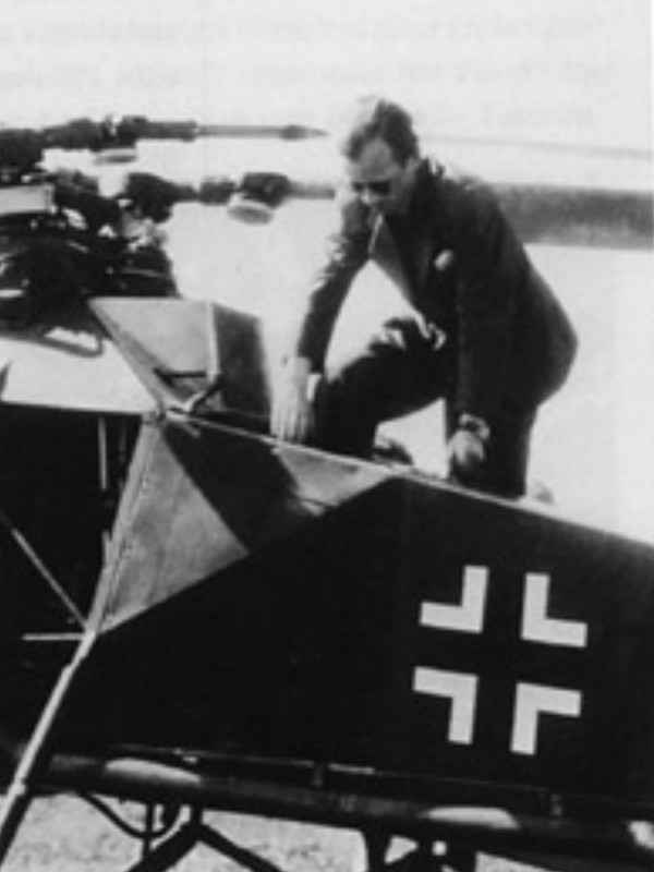
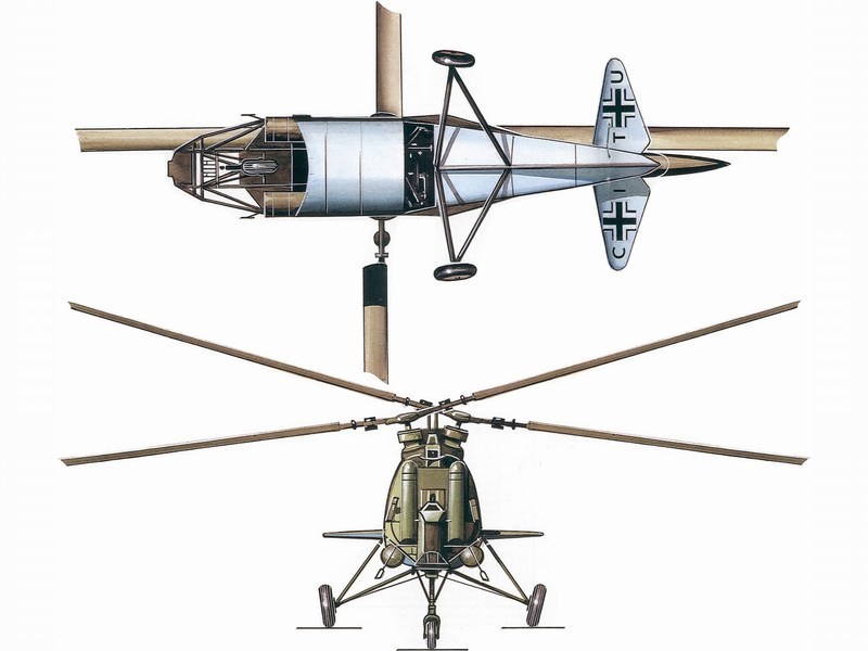
 The twin seat Fl-282 V21 helicopter registered as CI-TU, as seen while been tested with two men in rear compartment plus pilot. Anton Flettner himself took part on these test flights sitting in the rear observers seat and company chief pilot Oberleutnant (Luftwaffe 1st Lieutenant) Hans E. Fuisting on the flight controls. 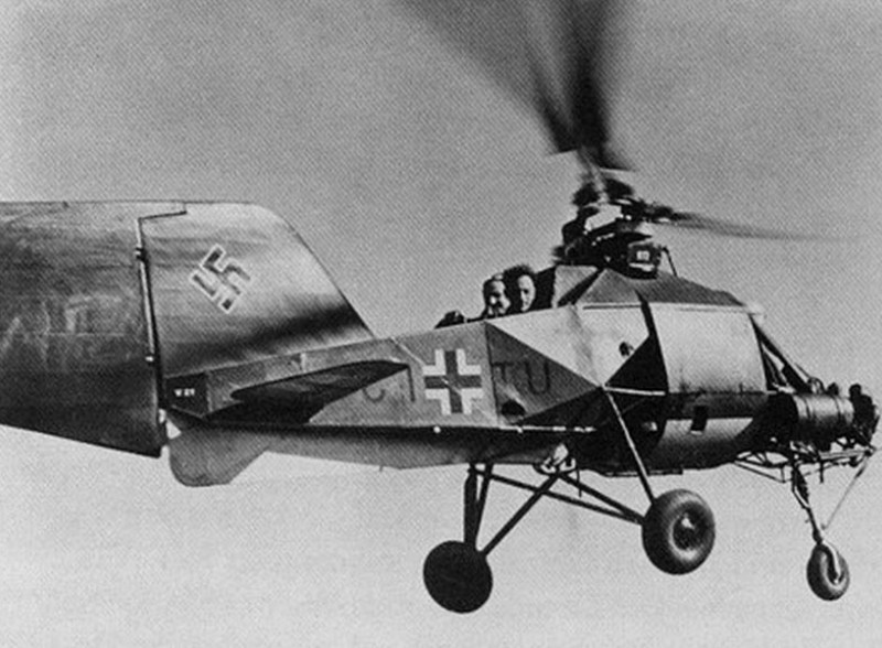
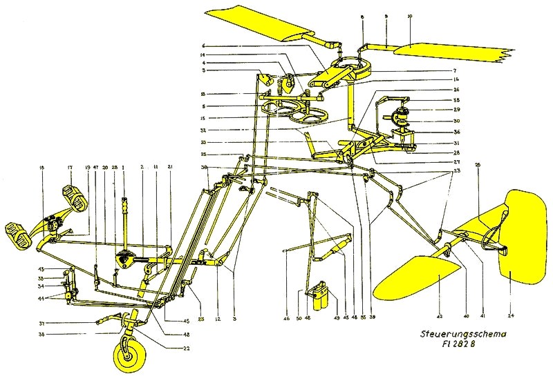
 The V23 version had also two seats for pilot & observer, but differed from V21 because it was equipped with V-shaped stabilizer (similar to that of the Cierva C-30) and also had wooden cockpit sidewalls, as visible into following diagram. 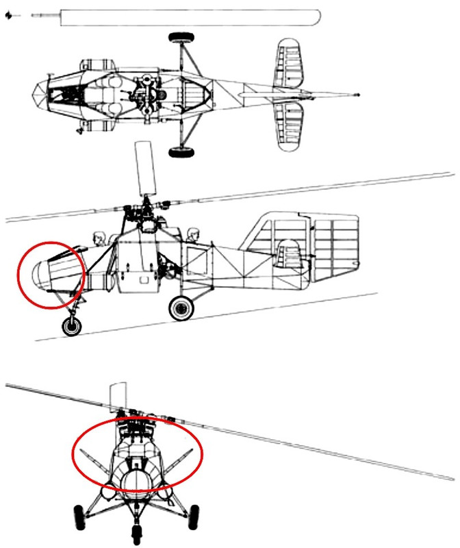 On June 22nd 1944 a mock combat between the Fl-282 V12 (registered as CJ-SF) with companys chief pilot Oberleutnant (Luftwaffe 1st Lieutenant) Hans E. Fuisting in controls and a FW-190 with pilot Oberleutnant (Luftwaffe 1st Lieutenant) Dieter Eisenlohr of Erprobungskommando (Testing Command) EKdo 25, took place at Schweidnitz, in order to investigate the chances of a fighter hitting a helicopter. A camera was installed in the wing of the FW-190 fighter, with the shutter release connected to the firing button. The combat was scheduled to last twenty minutes. During the first ten minutes, combat had to take place at altitudes above 330 ft (100 m). For the final ten minutes Kolibris pilot Hans E. Fuisting was advised that he could do as he wished. Camera film evaluation and both pilot written reports revealed that at altitudes more than 100 meters AGL (Above Ground Level) the fighter was able to get the helicopter in gun sights briefly but when near the ground, especially in difficult terrain, the fighter had little chance against a helicopter. The FW-190 pilot tried very hard and made the steepest possible turns to keep the helicopter into his gun sights. On the other hand, the Fl-282 helicopter pilot, only made slight evasive movements up, down or sideways so that he could escape from being into FW-190's gun sights. During the second part of the combat exercise, the Fl-282 helicopter simply vanished from the fighter, partly hidden between the trees as Hans E. Fuisting showed his mastery of nap-of-the-earth flying. FW-190s pilot Oberleutnant (Luftwaffe 1st Lieutenant) Dieter Eisenlohr's recollection of events is similar: ...At altitude above 330 ft (100 m) the Fl-282 seemed a small target clearly visible against the blue sky and I could partly compensate for Fuisting's evasive movements but during the second part of our combat, I had great difficulty spotting him in the meadows and forests around Schweidnitz. I twice spotted the Fl-282s because sunlight reflection on rotating blades & flat plexiglass panels of cabin and I had to make a 180° tight turn to try and get it in my gun sights... The June 1944 Monatsbericht (monthly report) of E-Stelle Travemunde noted: ...At present time, the evaluation of the film and the pilot reports have not arrived yet. At heights above 100 m the fighter was able to get the helicopter in its sights briefly. Near the ground, especially in difficult terrain, the fighter has little chance against a helicopter.... In following picture, the Fl-282 V12 (registered as CJ-SF) with partial plexiglass enclosure of the cockpit, as used on the June 22nd 1944 mock combat against a FW-190 fighter. 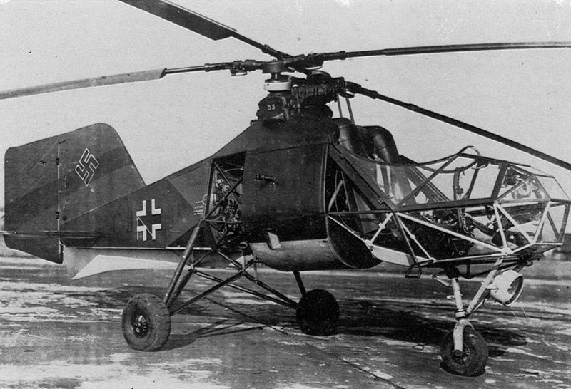 Vulnerability to gunfire was also investigated, whereby they proceeded on the assumption that the mathematical probability of a moving rotor blade being hit was much less than that of a fixed wing. Another consideration was that the helicopter could escape by making brief evasive movements, which the fighter could not follow. Furthermore, tests involving ground firing at the moving rotor blades were carried out, as the helicopter was felt to be more vulnerable to gunfire from the ground than from the air. An unmanned, tethered Kolibri was used; in spite of several hits in the rotor blades ground fire failed to bring down the helicopter. Good flight characteristics and easy handling in bad weather, led the German Air Ministry to issue a contract being given in 1944 to the BMW - Bayerische MotorenWerke for 1000 helicopters production. However, the factories based in Munich and Eisenach completely destroyed by the Allied bombing raids. The Flettner Johannisthal factory was also bombed and by the end of the War, this concern had completed only 24 operational helicopters (10 helicopters before 1943 plus 14 helicopters during 1943 & 1944). Due to the growing number of Allied air raids on Berlin, in August 1943 the company began transferring its operations to Schweidnitz in Silesia (approx. 50 km SW of Breslau); due to the deterioration of the transportation system the operation took several months. The Fl-282s on hand with the company were also flown to Schweidnitz to continue the test program. In February 1944 the workforce reached approximately 120 men, its highest level ever. With the Red Army approaching Silesia, the company moved back to Berlin Tempelhof in January and February 1945. Any systematic work or further production was of course out of the question under these circumstances. To make matters worse, two days after its arrival the rest of the company's equipment was destroyed in a night raid on Tempelhof. What was left of Anton Flettner Flugzeugbau GmbH was subsequently evacuated to Bad Tölz (Upper Bavaria); two Fl-282s were also flown there. The story Anton Flettner Flugzeugbau GmbH ended there with the arrival of US Army troops. 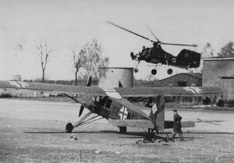 |
Mesajı Yazan: Nick_Karatzides
Mesaj Tarihi: 10/08/2014 Saat 19:06
|
Towards the end of World War II, most of the surviving Flettner Fl-282s were stationed at Rangsdorf AB & Ainring AB at Mühldorf, Bavaria, in their role as artillery spotters, assigned to TransportStaffel (transport squadron) TS40, the Luftwaffe's only operational helicopter squadron but gradually fell victim to Soviet fighters and anti-aircraft fire. During the last few months of the War the Luftwaffe's TransportStaffel TS40 squadron made many flights into and out of besieged and encircled towns transporting dispatches, mail and key personnel. It was possibly one of this unit's Fl-282s that flew Gauleiter (governor of Lower Silesia, Bavaria), Reichsführer SS and Chief of the Deutschen Polizei http://en.wikipedia.org/wiki/Karl_Hanke - Karl August Hanke , to his escape out of besieged Breslau, on May 5th 1945, letting him escape to Prague, just one day before the capture of that city. It seems that it was the CI-TU registered Fl-282 V21, as the only available two-seater helicopter in squadron that date, since the other V23 (registered as CI-TW) two-seater, had been flown away and hidden at Bad Tölz few days earlier (on April 26th 1945 flown by companys chief pilot Hans E. Fuisting). By May 7th 1945, the Soviets were located less than 19 miles away from Fl-282 base and orders were received to transfer westward to avoid capture. On May 8th 1945, the ground element of TransportStaffel TS40 set out by road to Zell-am-See. Since there were no available pilots for the remaining Fl-282s, attempts were made to destroy the helicopters. Unfortunately, very few Fl-282s survived the War and only five found by the Allies in a serviceable condition for testing and evaluating. Also unfortunately, the Fl-282 helicopter was not so much photographed and there are not available photographic records of each one of these 24 helicopters produced. Actually, the total (known) photographs while serving under Kriegsmarines & Luftwaffes markings, might not exceed total 100 - in which more usual protagonists are the V6 (naval tests) and the V21 (double seats), both typical examples of the type but both did not survive the War.
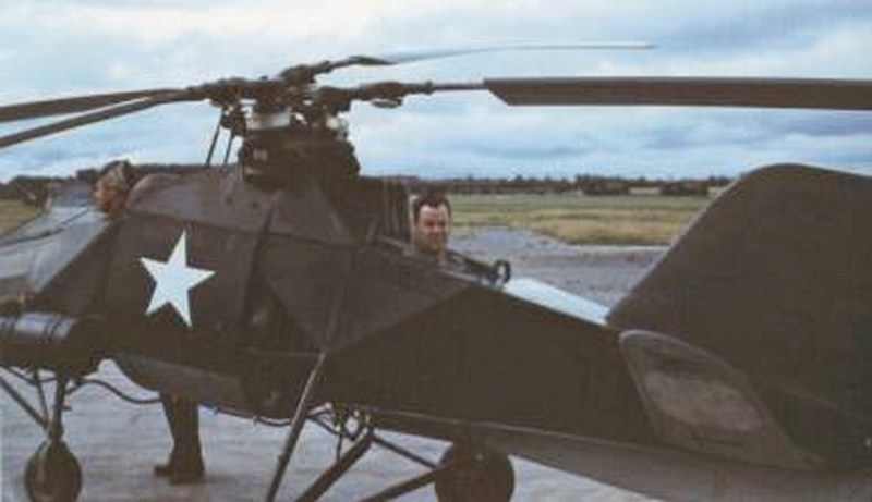
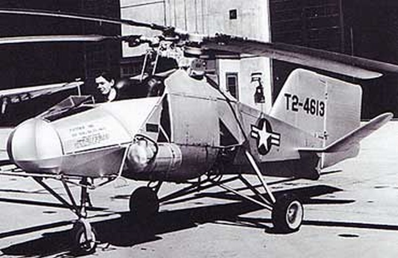
Captured helicopters #1 & #2: The first two flyable helicopters were found intact by US Army troops. One V23 helicopter registered as CI-TW and one V15 registered as CJ-SI. These two Fl-282s, received the FE-4613 and FE-4614 US numbers after been captured and transported from Cherbourg Octeville, France to Newark New Jersey, USA (Operation Seahorse from July 12nd 1945 to July 19th 1945) aboard HMS Reaper D82 (a Bogue class escort aircraft carrier of US Navy, leased to the Royal Navy during WWII) for further investigation. The Fl-282 V23 Kolibri was a two-seater similar to the V21, with V-shaped stabilizer fins. Into following pictures, notice the exact same V23 helicopter as seen with pre-capture Luftwaffes CI-TW registration & swastika markings and later in USAAF service with the FE-4613 US numbers visible, after been captured. 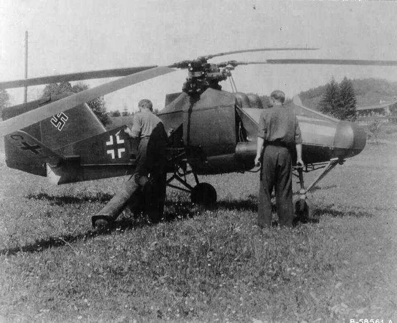
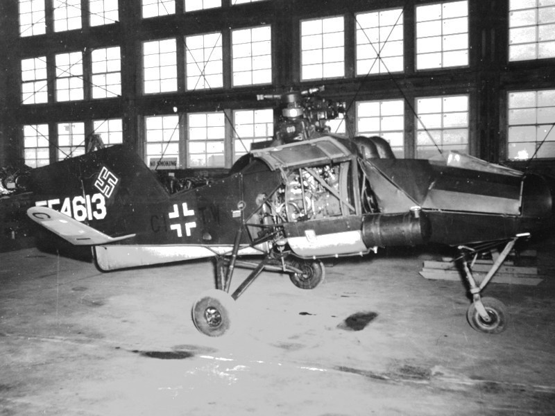 These two Fl-282s found & captured by the US Army troops were actually revealed by Anton Flettner himself. These two helicopters were flown from Schweidnitz to Bad Tölz, few days earlier, on April 26th 1945. The first (CI-TW registered V23) flown by companys chief pilot Oberleutnant (Luftwaffe 1st Lieutenant) Hans E. Fuisting, was hidden in a barn near Bad Tölz. The other (CJ-SI registered V15) helicopter flown by pilot Ernst Remain, was hidden in a mill near Penzburg, 15 km west of Bad Tölz. Following the arrival of the US Army forces, Anton Flettner reported the hiding places to the US military administration in Bad Tölz. The two US held Fl-282s were first taken to Munich and then to Stuttgart (Nellingen flugplatz) where been demonstrated to Allied officers by German pilots. Since USAAF officers were impressed with the helicopters, the captured Fl-282 V23 (CI-TW / FE-4613 registered) Kolibri transferred to St. Dizier, France on June 15th 1945 and been demonstrated by Anton Flettners chief pilot Oberleutnant (Luftwaffe 1st Lieutenant) Hans E. Fuisting. By December 1945, the Air Technical Intelligence collection and evaluation process for Luftwaffe technology officially transferred from London, UK to Wilbur Wright Field (officially Area B of Wright Patterson AFB) near Riverside Ohio, USA. 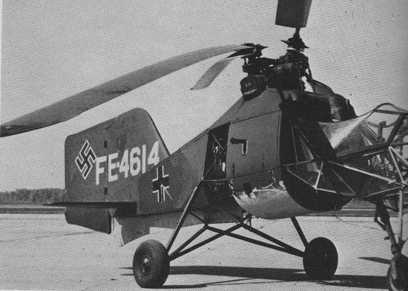
 The evaluation flights in US (115 hours) were conducted at Benedict airport, Booth Corners Pennsylvania, USA by Prewitt Aircraft company test pilot Captain Dave Driskill. The objectives of the tests were to determine power requirements, control response, stability measurements & a comparison between a straight and a V-shaped stabilizer. In March 1946, the Air Technical Service Command became Air Material Command and it was around this time the FE numbers, assigned to captured Luftwaffe aircrafts, became T2 being the organization designator for Air Technical Intelligence. The prefix FE (meaning Foreign Equipment) changed to T2 but the inventory numbers did not change. This probably reflected the organizational changes taking place. Now days, the Fl-282 V15 is presented at the Cranfleld Institute of Technology. On the other hand, although the V23 helicopter was transported and placed at the http://www.nationalmuseum.af.mil - National Museum of the United States Air Force , located at Wright Patterson AFB 6 miles NE of Dayton Ohio USA, its current whereabouts are unknown. 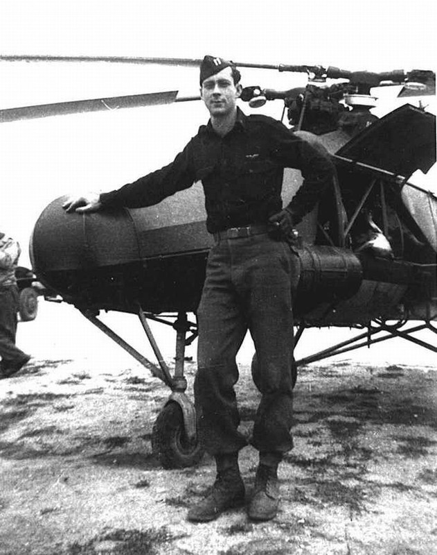
 Captured helicopter #3: On May 9th 1945, pilot Max Schmid (pictured in following photograph) trying to escape capturing by Red Army, flown with the CI-TV registered V22 helicopter to his home village of Wallern (about 130 km SE of Vienna, Austria) to rejoin his wife & children. He landed at his family farmhouse backyard and with the help of his wife he managed to hide the helicopter in the barn. Unfortunately his flight did not go unnoticed and soon US troops arrived and arrest him. Max Schmid refused to fly and demonstrate the Fl-282 for the Americans. Instead he helped them dismantle the Kolibri for transport. Unfortunately, no more info is available about the fate of Max Schmids CI-TV registered Fl-282 V22 helicopter after the War. 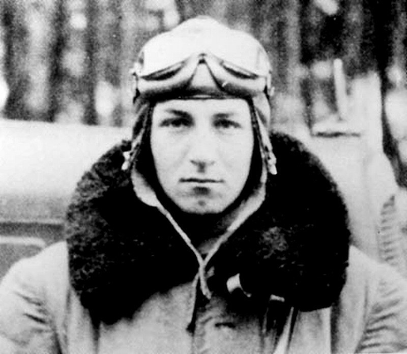 |
Mesajı Yazan: Nick_Karatzides
Mesaj Tarihi: 10/08/2014 Saat 19:22
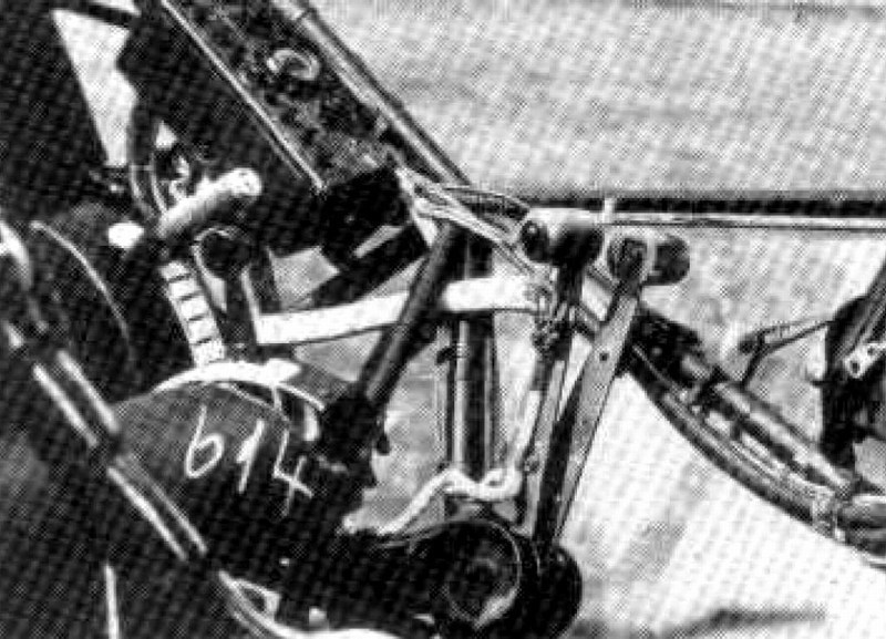
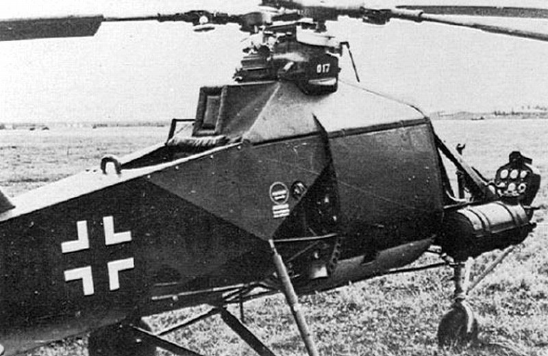
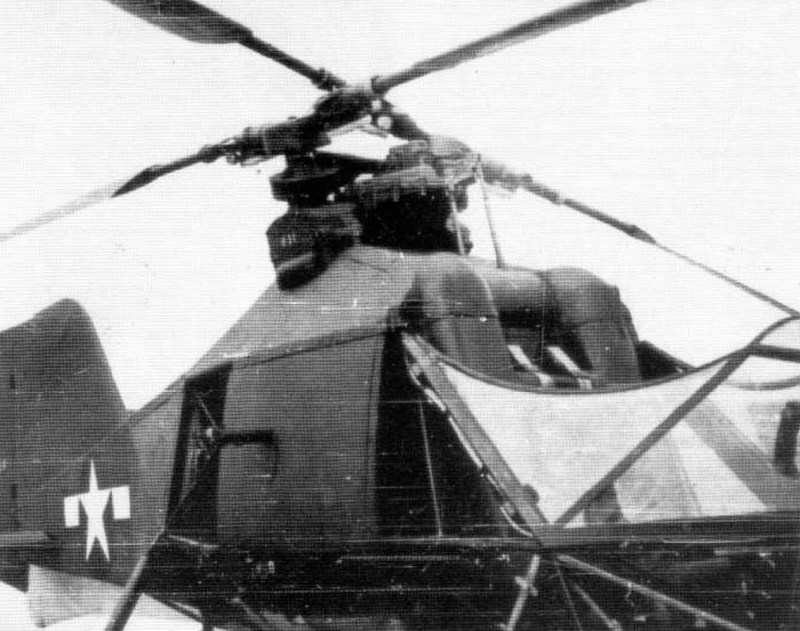
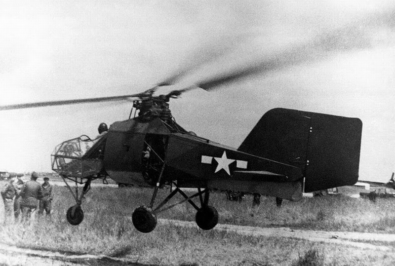
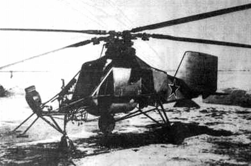
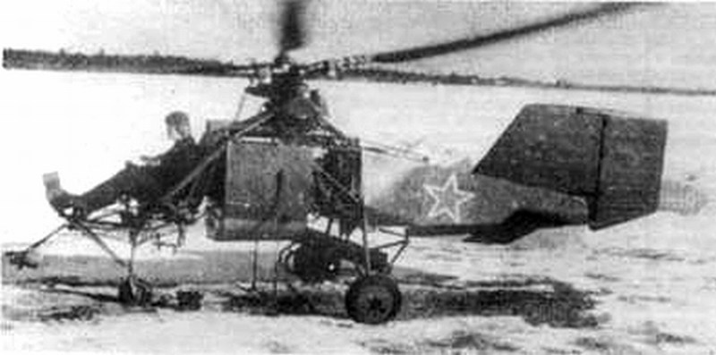
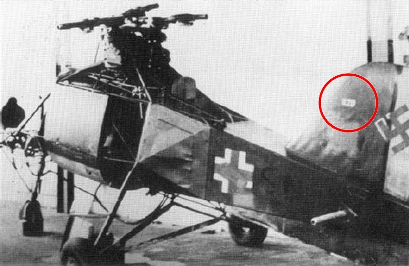
Captured helicopter #4: It is reported that another Fl-282 helicopter which had been assigned to TransportStaffel TS40 was captured at Rangsdorf by Red Army forces in serviceable condition and later transferred to USSR for further testing & evaluation. Judging by the following pictures, its a B-0 series (without partial plexiglass enclosure of the cockpit), single seat helicopter and could possibly be the V13 (CJ-SG registered) or the V14 (CJ-SH registered) or the V16 (CJ-SI registered) or the V18 (CJ-SL registered) helicopter. The first two helicopters should be excluded because Luftvaffes files reveal that the V13 & V14 were both unserviceable & grounded that time (V13s rear fuselage and V14s rotors removed to be used as spare parts on other helicopters). This means that the pictured Soviet captured Kolibri might was the V16 or the V18 helicopter (both previously assigned to Staffel 1/196 at Pillau AB and Grouppe 3/196 at Kiel). Another possible answer for the mysterious helicopter could be the V11 (registered as CJ-SE) property of Anton Flettner Flugzeugbau GmbH company and used as testbed, later transferred to TransportStaffel TS40 stationed at Rangsdorf AB, but it was also reported to be grounded because had no engine installed that time. On the other hand, there is a possibility that the helicopter appeared to be captured by Soviets, could be a B-1 series machine, for example the V12 (CJ-SF registered) helicopter survived until the end of WWII, with the cockpit glazing removed by Soviets later. Keep in mind that the V16 helicopter was also considered as the Soviet captured Kolibri by RS Models, also pictured on their 1/72 scale Flettner FL-282 B-0 Kolibri model (companys code http://rsmodels.cz/cs/modely-letadel/plastikove-modely/1-72/92083 - 92083 ) instructions sheet. According to RS Models, the V16 was transferred to Sukovskoje, USSR and evaluated until 1947. Anyway, since no more info is available about the Soviet held Fl-282 helicopters fate after the WWII, we cannot be absolutely sure for a positive ID.
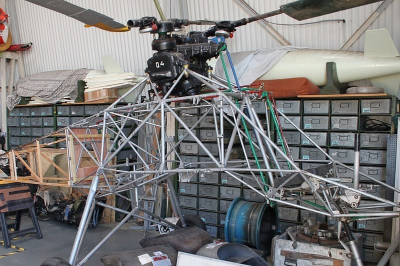
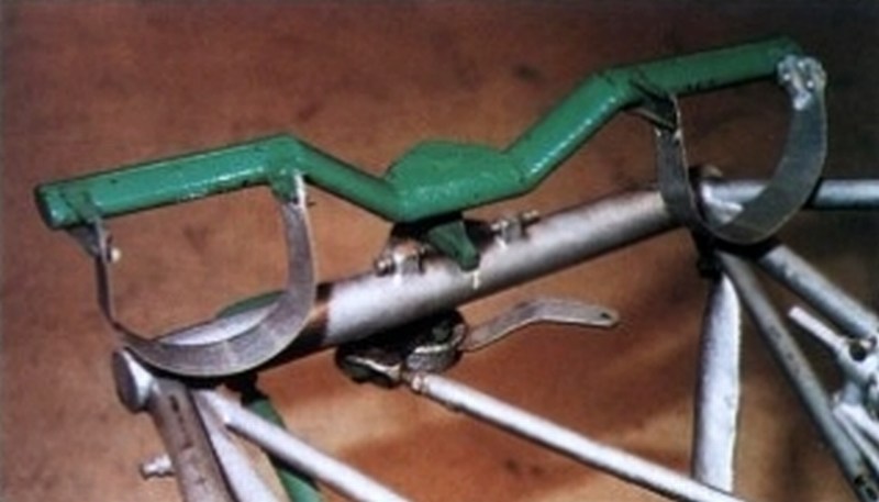
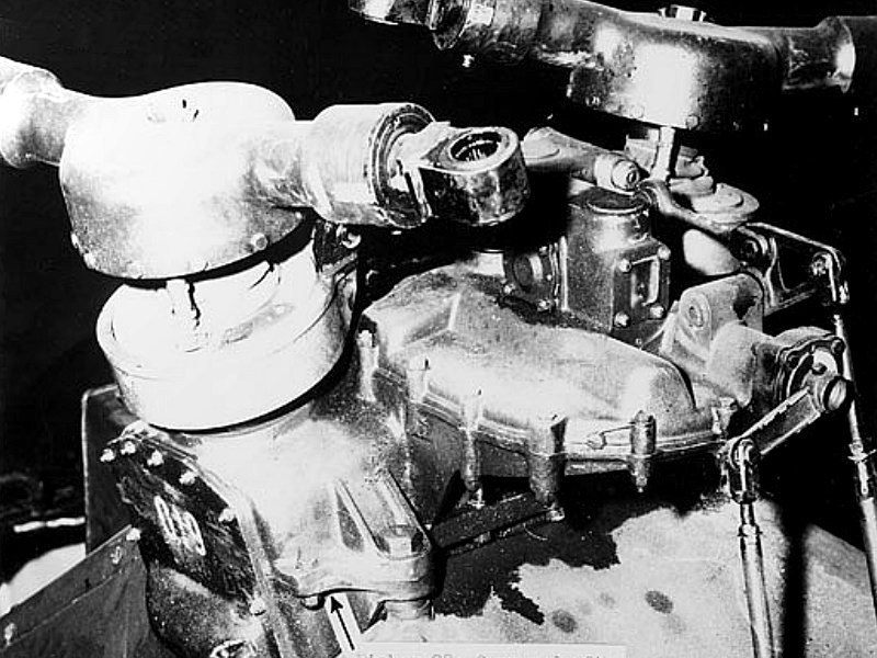
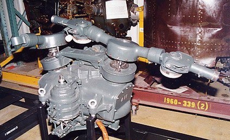
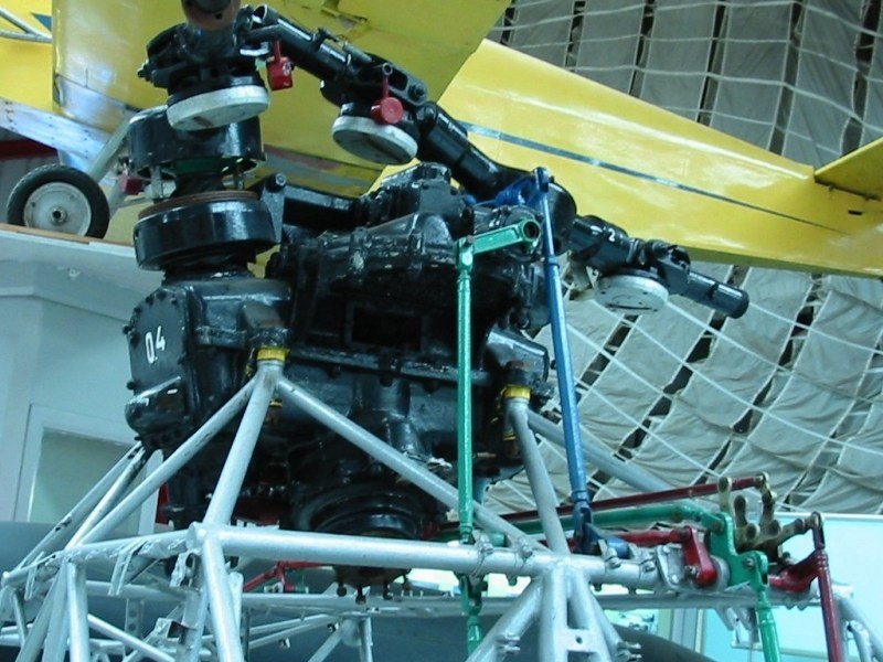
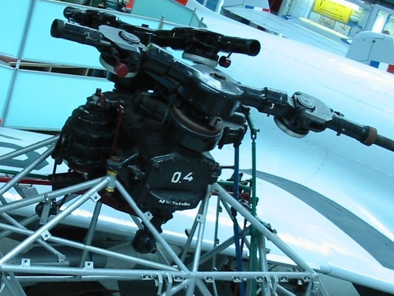
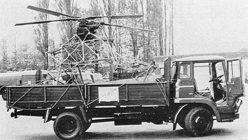
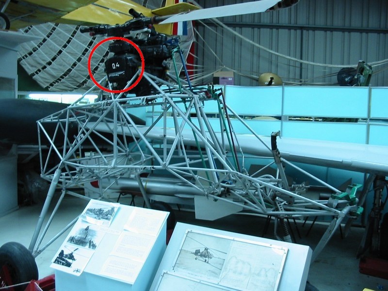
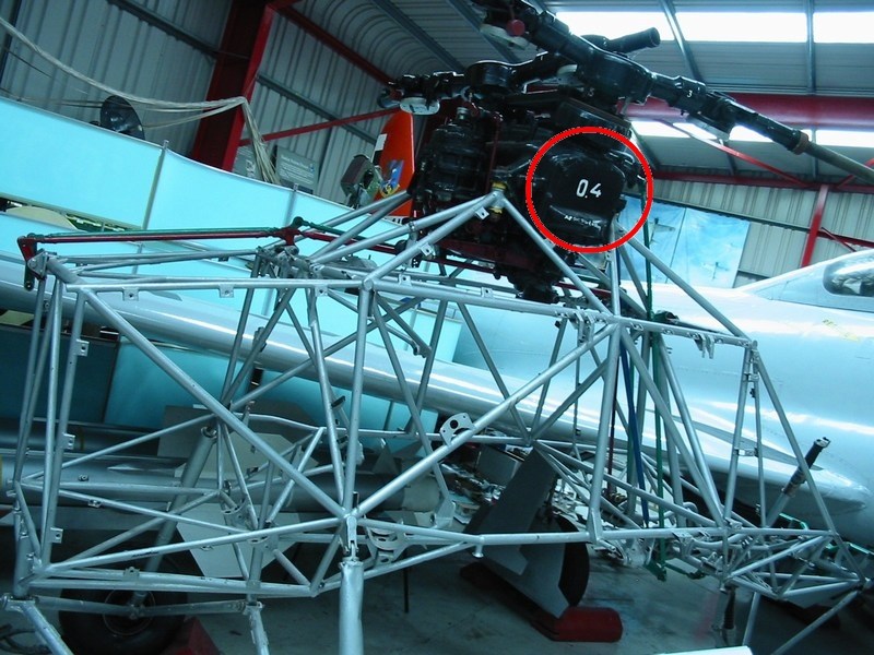
 Captured helicopter #5: Finally, a fifth Fl-282 V20 helicopter (registered as CJ-SN) previously assigned to Staffel 1/196 at Pillau AB, found & captured by the British Army in good condition. For some unexplained reason, the helicopter been brutally disassembled and some parts of it ended up as souvenirs. The doped fabric ripped away & removed from fuselage, the horizontal stabilizer fins mysteriously stolen, the clipped rotor blades cut off and are never seen again since that day. The remaining framework wreckage with upper rotor transmission, transferred back to UK as a War trophy, on late May 1945. Notice the 04 which indicates the serial number of the upper rotor transmission as pictured right after been found and next photographs as finally disassembled & transferred on a truck by British troops as War trophy. Upon arrival in UK, this exact helicopter Fl-282 V20 relic became property of the Cranfield College of Aeronautics until mid 1960ies, when sold to Midland Air Museum. Now days, the captured V20 helicopter fuselage framework parts with upper rotor transmission and what left of the chopped (once full-length) rotor blades, are presented at the http://www.midlandairmuseum.co.uk - Midland Air Museum situated just outside the Baginton village in Warwickshire, UK and is adjacent to Coventry, UK airport. Unfortunately, many parts are still missing and the doped fabric cover & rotor blades never been restored. 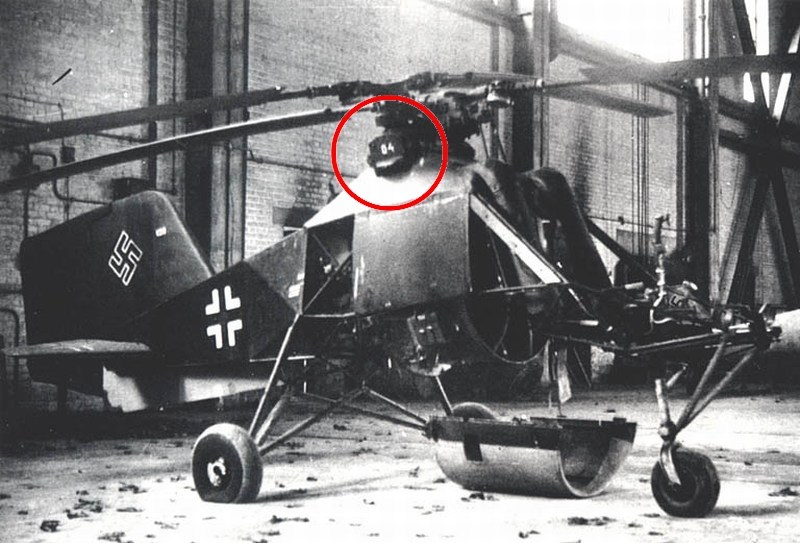
 The technical data & general characteristics are: - Type designation: Flettner Fl-282 V21 Kolibri, - Country of production: Germany, - Usage: ASW / Reconnaissance helicopter, - Crew: 1 pilot & 1 observer (on V21 & V23 versions), - Year of construction: 1940 - 1945, - First flight: October 30th 1941 flown by test pilot Ludwig Hoffmann, - Length: 21 ft 6 in (6.56 m), - Height: 7 ft 3 in (2.20 m), - Rotor diameter: 2 x 39 ft 3 in (11.96 m), - Rotor area: 2418.5 ft² (224.69 m²), - Rotor turns: 175 rpm for best cruising / 180 rpm at takeoff, - Rotor blade chord: 11.42 in, - Rotor loading: 1.81 lb/ft² (8.84 kg/m²), - Powerplant: 1 x Bramo Siemens Halske SH-14A, 7-cyl aircooled radial engine of 119 kW (160 hp), - Weight empty: 1676 lb (760 kg), - Weight max takeoff: 2205 lb (1000 kg), - Armament: 2 x 5 kg explosive bombs or magazine for 4 smoke buoys, - Fuel tank capacity: 27.8 gal (105 lt) if pilot only / 17.2 gal (65 lt) if both pilot & observer, - Fuel consumption: 8.5 gal/h when flying 60 km/h (economic cruising speed), - Speed maximum forward: 93 mph (150 km/h) at sea level, - Speed maximum backward: 30 mph (48 km/h) at sea level, - Speed maximum sideways: 20 mph (32 km/h) at sea level, - Speed maximum gliding as autogyro: 60 mph (97 km/h) at sea level, - Range operational: 186 miles (300 km) if pilot only / 112 miles (180 km) if both pilot & observer, - Endurance operational: 1.5 to 3 hrs depending on cruising speed & altitude, - Ceiling service: 10827 ft (3300 m), - Ceiling hover: 984 ft (300 m), - Rate of climb: 299 ft/min (1.52 m/s). 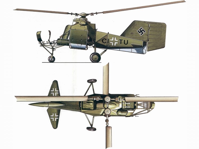
 |
Mesajı Yazan: Nick_Karatzides
Mesaj Tarihi: 10/08/2014 Saat 19:26
|
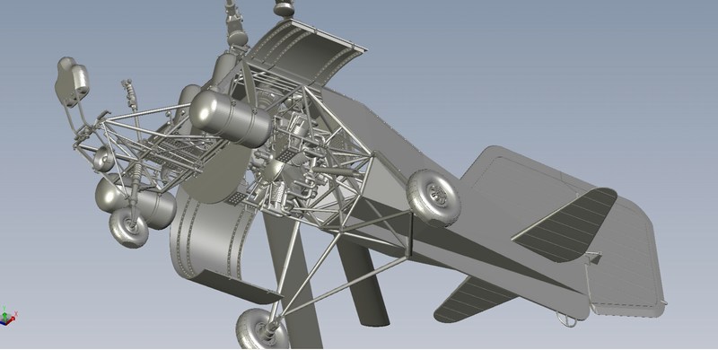
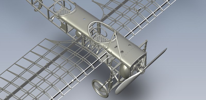
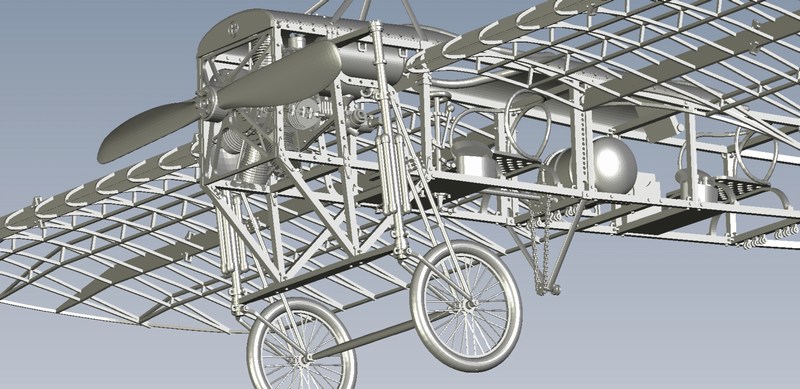
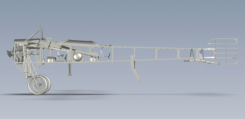
Before start building a new scale model, I always try to study as much as possible the object of construction. Any available references such as technical manuals and detailed photos always help during building process. As described into my previously uploaded WIPs into this forum (feel free to have a look on the IS-A Salamandra glider and the Wallis WA-116 autogyro 3D printed models under 1/18 scale), the plan is to design a detailed CAD file and then print it, on a 3D replicator. Following this method helps a lot and gives the opportunity to scratchbuild almost anything, under any scale, within short time. The 3D printing technology introduction into scale modelling and free access to the average modeller is a great evolution in the hobby and a creative tool that helps us to build better and more realistic models. Certainly the new technologies and gadget tools in the hands of talented enthusiasts open new horizons and provide almost unlimited potentials on scale model building. 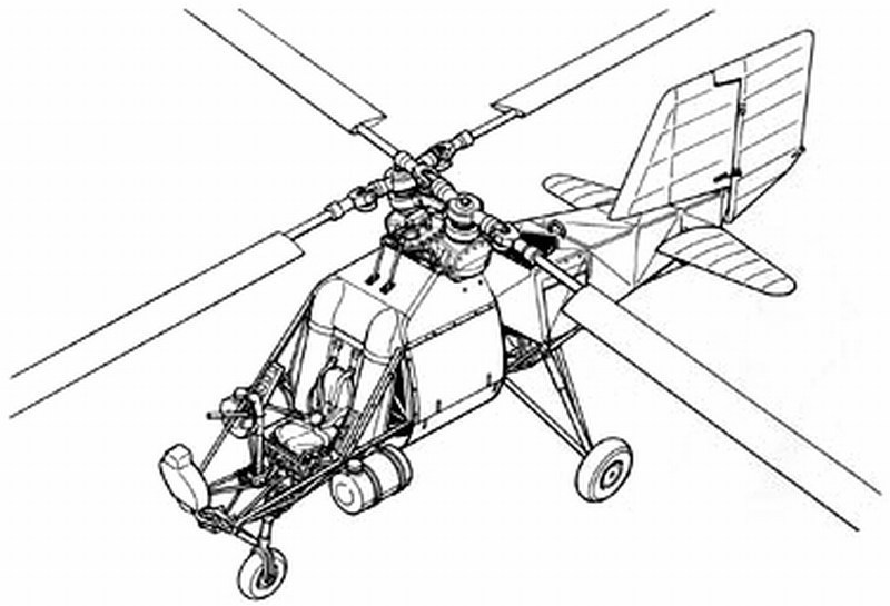 Because the detail complexity of the model, the present Kolibri project took approx 150 hours of computer work, to CAD design within a hundredth of a mm accuracy, scale into correct 1/18 size and then digitally cut the helicopters compartments into virtual pieces, having always in mind that the later 3D printed parts, should perfectly fit and finally become a fine scale model. Most amazing part is that after the CAD file is ready, the model can be produced under any scale, as many times as you like, just by clicking a button. And voilà, a new digitally created Flettner Fl-282 Kolibri model is ready to be forwarded to the 3D replicator and become an actual physical object under 1/18 scale, within short time. 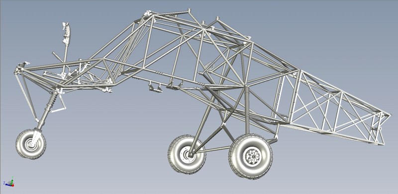
 |
Mesajı Yazan: Nick_Karatzides
Mesaj Tarihi: 10/08/2014 Saat 19:41
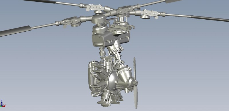
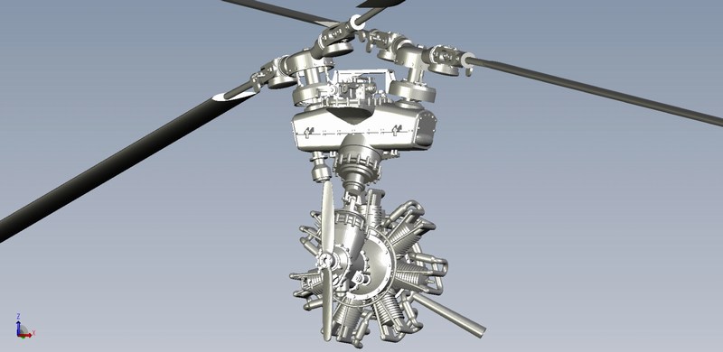
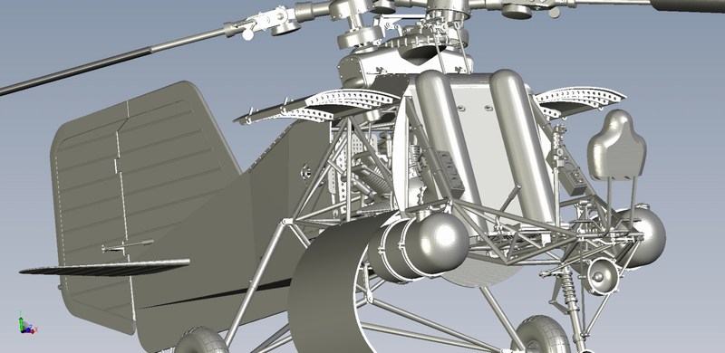
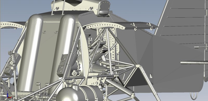
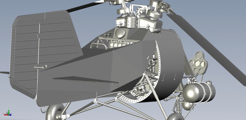
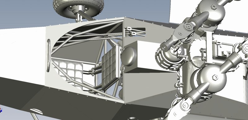
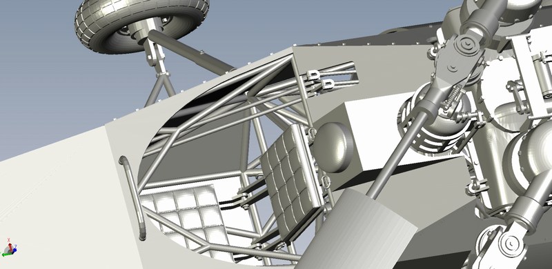
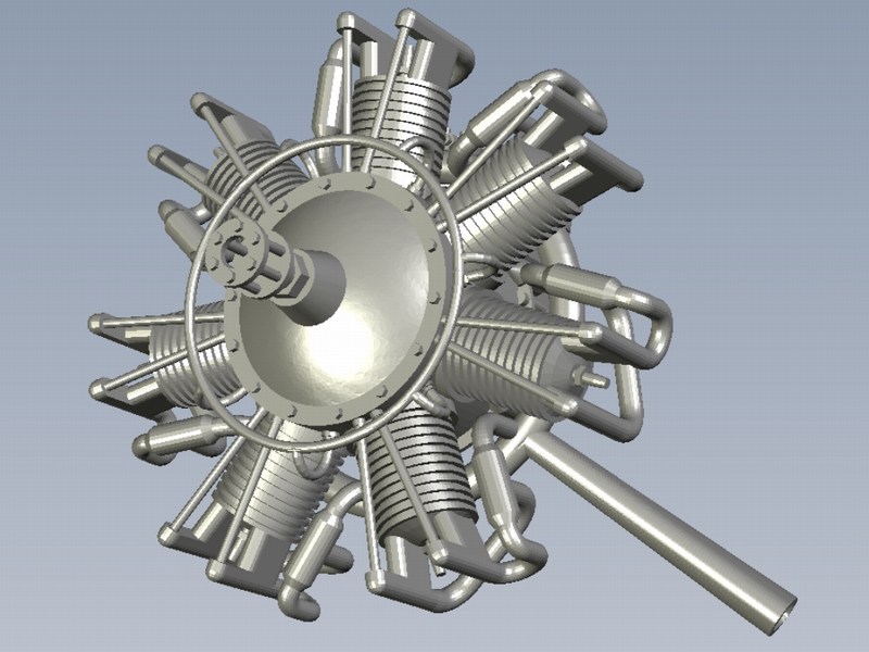
This is the complex of intermeshing rotor gearbox. It turned out (as happened in the actual helicopter) that it was the hardest and most complicated part to build, because it was not easy for me to get a technical manual describing the gearbox in detail. Fortunately (thanks to Deutsches Marinemuseum), I managed to get access to blue prints and some detailed photographs, which helped me a lot to understand exactly how it was in reality and to ascribe it as accurate as possible to a scale model part. Because I was never completely satisfied with outcome and had to delete it and start over again and again few times, this damned thingy took me more than 25% of total CAD designing time.
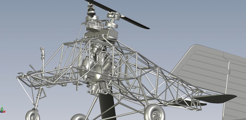
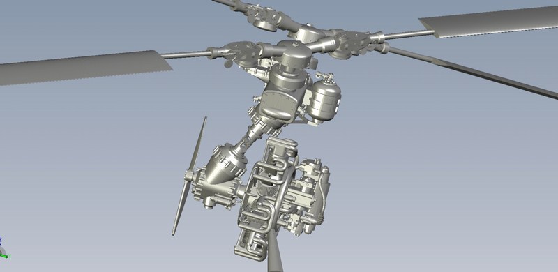
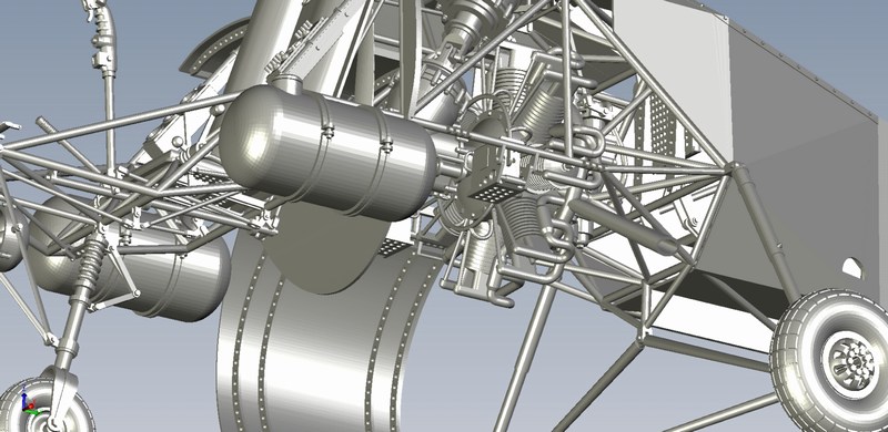
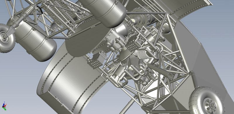
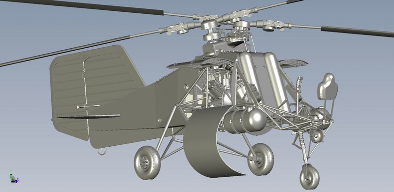
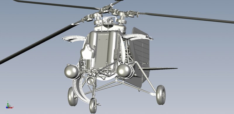
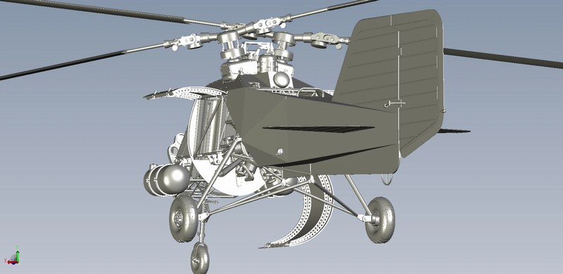
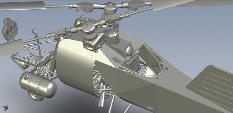
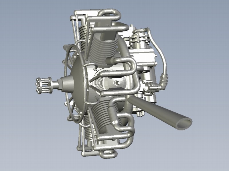
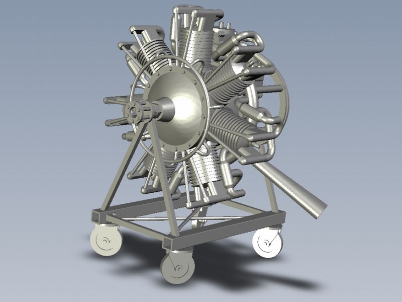
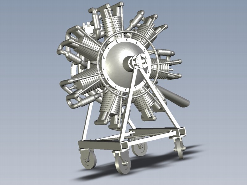
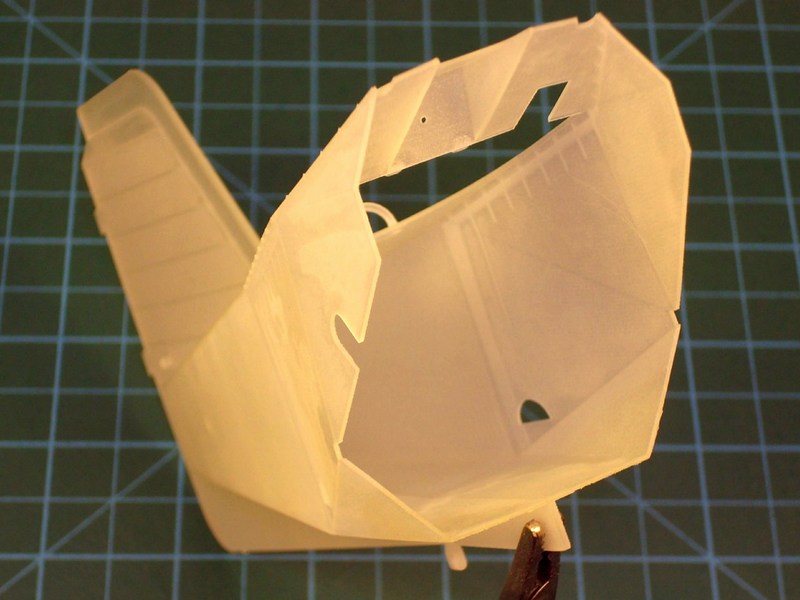
 Since the oval cross-sectioned central fuselages outer skin consists of removable doors, hoods & sliding panels, I designed the CAD file such way to set all hatches in opened position and present it as during maintenance. For this reason, the 7-cylinders radial engine can be removed from helicopter and be placed nearby on a wheeled stand. Actually, by this way (not necessarily planned to create some diorama scene) the models observer can easily have a closer look inside the helicopters belly and also check detail on the (visible by any angle) engine details same time. 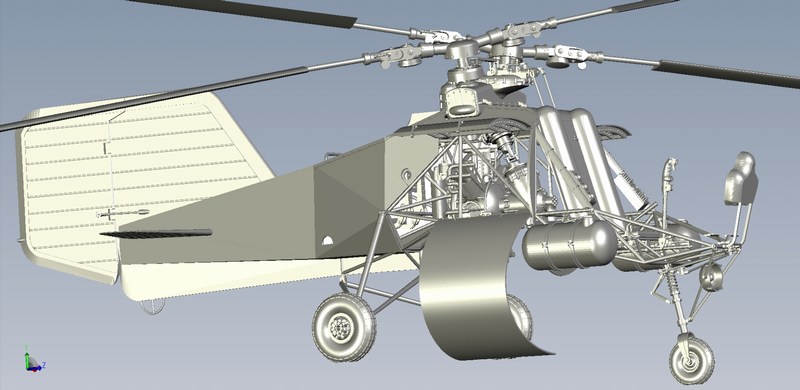

 |
Mesajı Yazan: Nick_Karatzides
Mesaj Tarihi: 10/08/2014 Saat 21:06
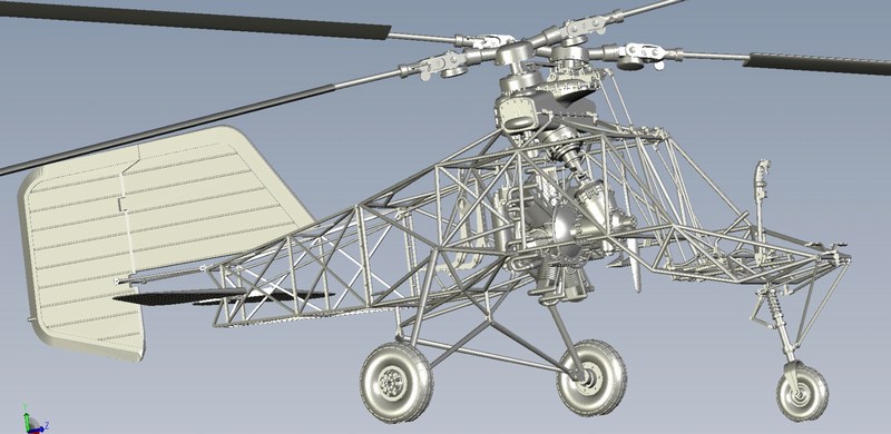
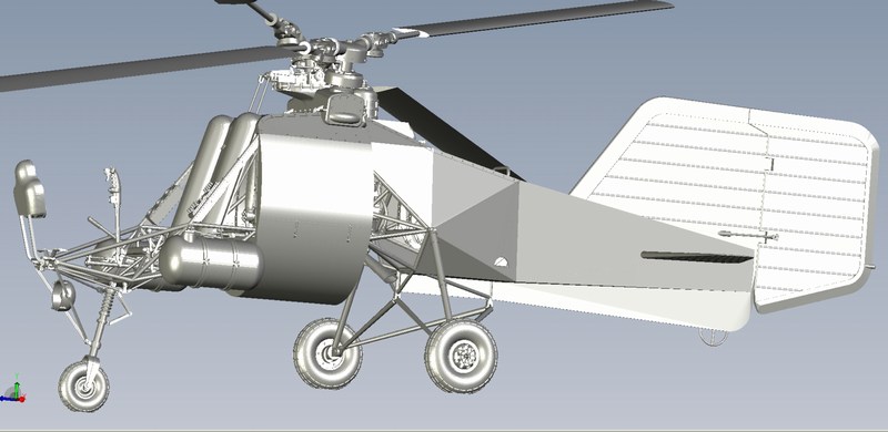
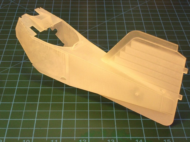
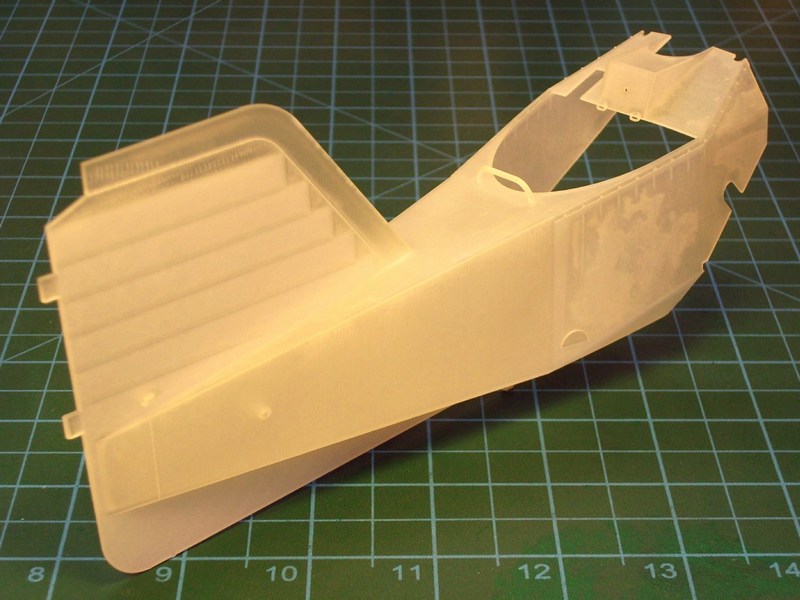
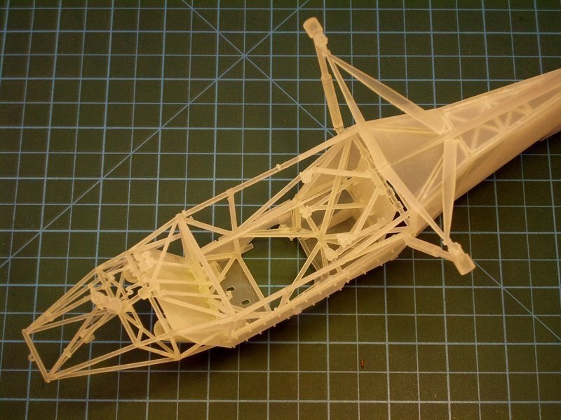
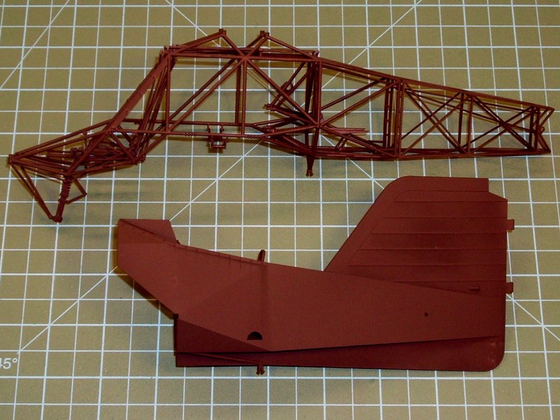
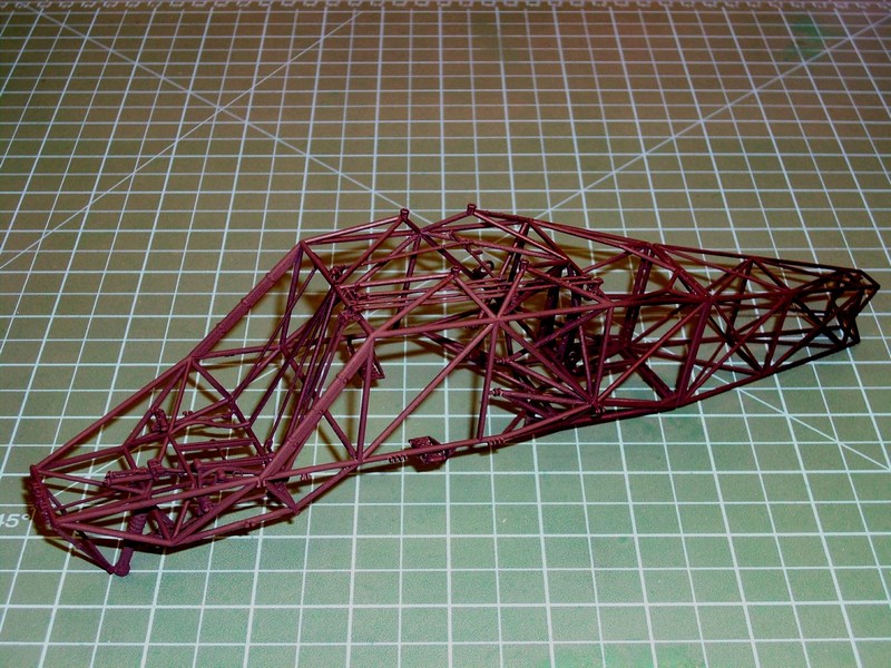
The biggest part of the kit are the 4 rotor blades measuring approx 28 cm long each. The fuselage was CAD designed such way and later 3D printed into two main section parts with all included truss-type welded tubes and drive shaft rods with universal joints inside. That was mostly preferred for me, because all basic parts should be accurately pre-installed in place without any glue, putty, sanding etc. On the other hand, that could arise some minor difficulties while painting, but I think that proper masking & airbrushing could lead on good results.
 |
Mesajı Yazan: Nick_Karatzides
Mesaj Tarihi: 10/08/2014 Saat 21:40
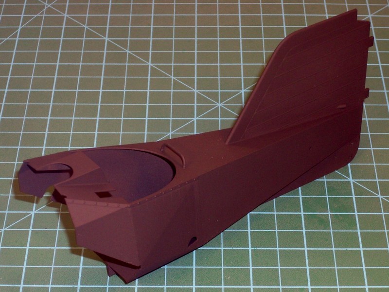
The doped fabric cover over the truss-type welded tubes & wooden ribs is about 0.4 mm thick (in some special areas about 0.7 mm). Thinking as a rivet counter, this 0.4 to 0.7 mm thick fabric cover could be considered as an out-of-scale unforgivable mistake, having always in mind that it does represent a fabric material and it should normally be as thin as the air. On the other hand, the whole construction should be structural reinforced somehow and making the fuselage skin even thinner than 0.4 mm, might result a major building failure. Anyway, I think that 0.4 mm is just fine, considering that all the well known Tamigawas mass produce and sell model kits with much more thick fuselage skins than my custom made Fl-282 and no rivet counter complains about it. Right?
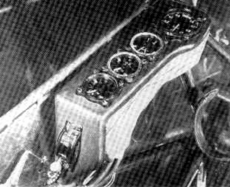
 Engine throttle & rotor collective levers with panels for auxiliary gauges placed on each side of pilots seat. Electric wiring for switches and gauges cables will be added later. 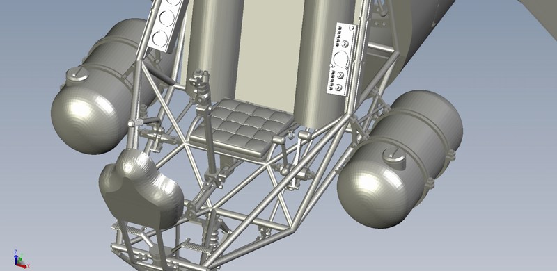
 |
Mesajı Yazan: Nick_Karatzides
Mesaj Tarihi: 10/08/2014 Saat 21:58
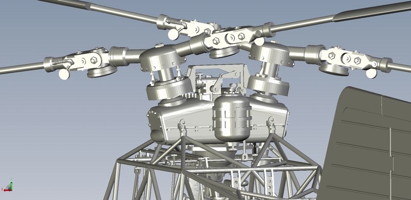
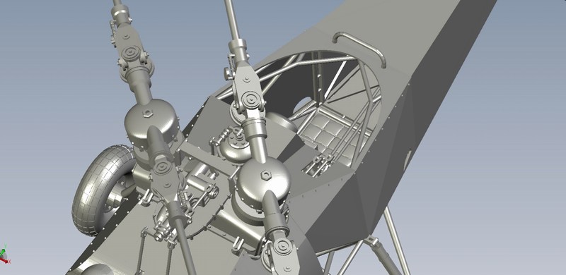
This is the 3D design of one of the two rotor heads, equipped with vibration dampers pots on the blade roots. Each one of the separately 3D printed rotor blades, will be later attached on the blade root connecting hinges and the outcome will be installed on gearbox shafts, having an included angle of 24° between the two rotor heads and an inclination forward of 6°.
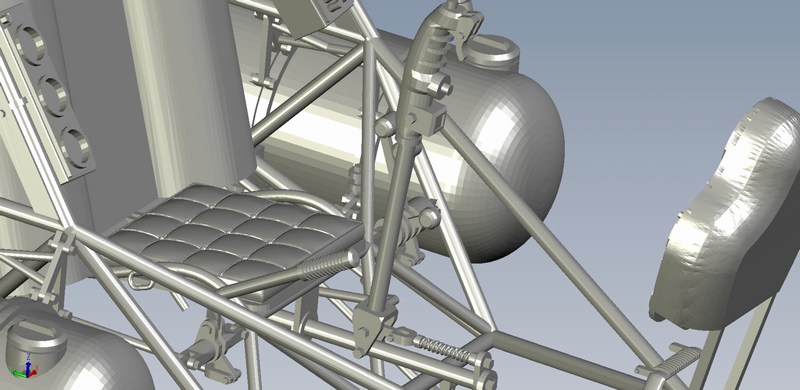
 Totally four seat frames produced. One for the single seat V6, another two for the double seater V21 model and an additional one for spare in case something breaks. These seat frames are only 0.6 mm thick and proved to be much stronger than expected. 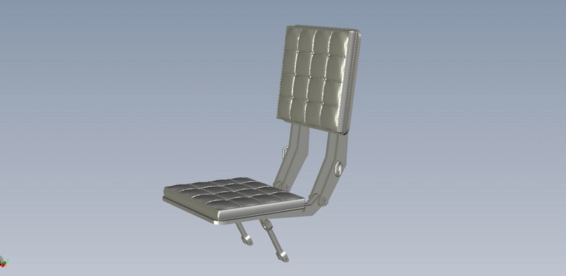
 The main instrument panel with opened areas for gauges and 0.2 mm embossed detail around it to simulate the support bezels. Each gauge was 3D printed separately and will be added later, after placing the proper water slide decals. 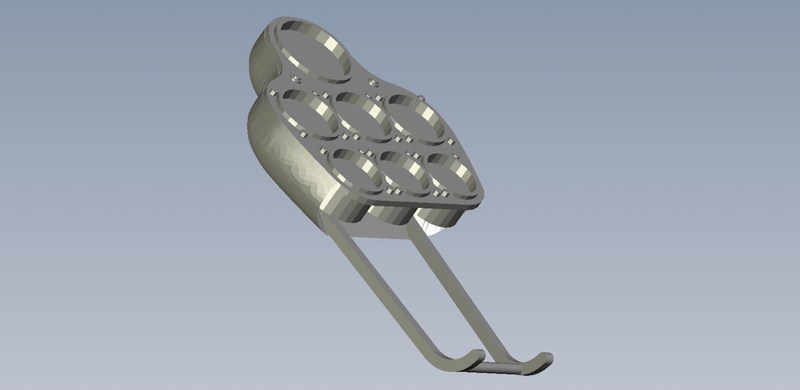
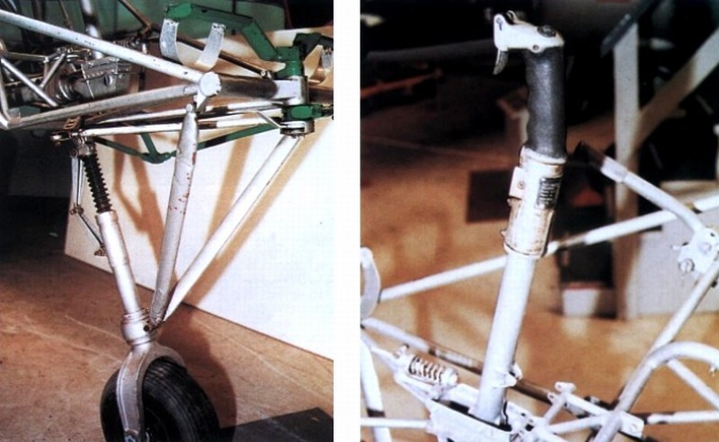
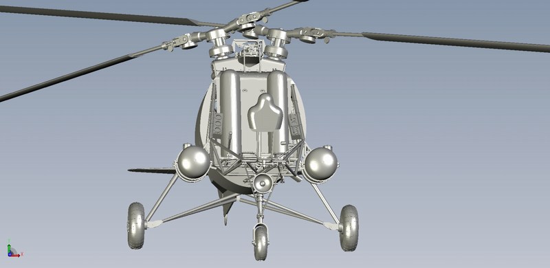
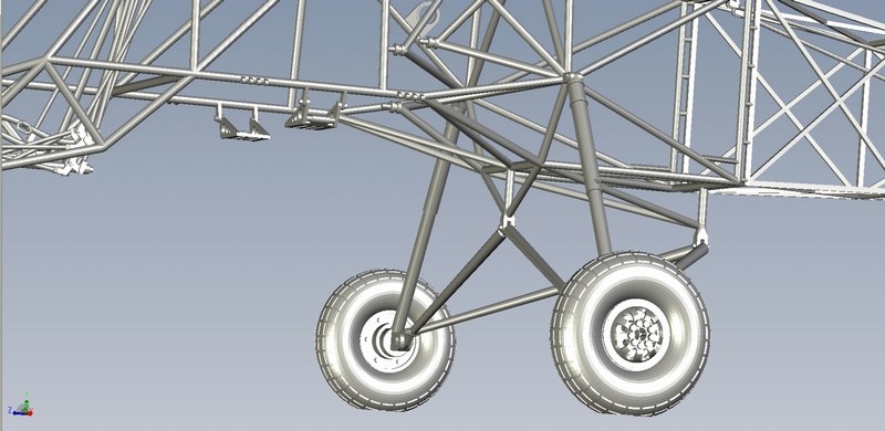
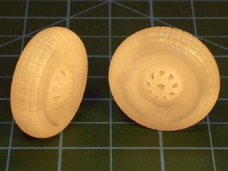
 Most of available B&W and some coloured (during evaluation flights in USA) photographs are not detailed enough to reveal if the landing gear wheels had engraved tread grooves (and how many) or embossed lugs running circumferentially around the tire. The Fl-282 wheels found nowadays in museums could not be considered as a reliable reference, because the original tires could not last after 70+ years and would probably be replaced by other similar size & shape. Anyway, since I was aware for the exact 350x150 mm size for the nose wheel and 465x165 mm size for the main gear tires, I created a set of wheels, which looked realistic to me. Also, in most pictures the helicopters seemed to have slightly conical shaped caps installed over wheel rims, but there are also some pictures revealing uncovered wheel rims. Having these photos in mind plus some diagrams of Fl-282s undercarriage system, I thought that it would be quite interesting and challenging to present the wheels without rim caps. 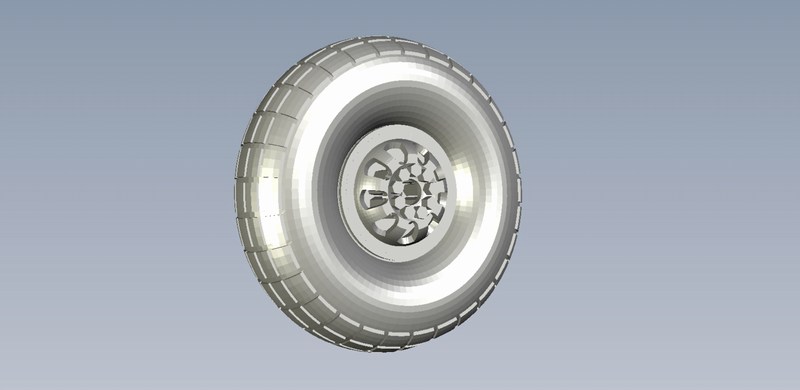
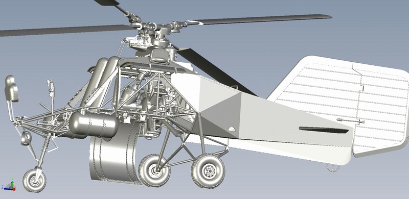
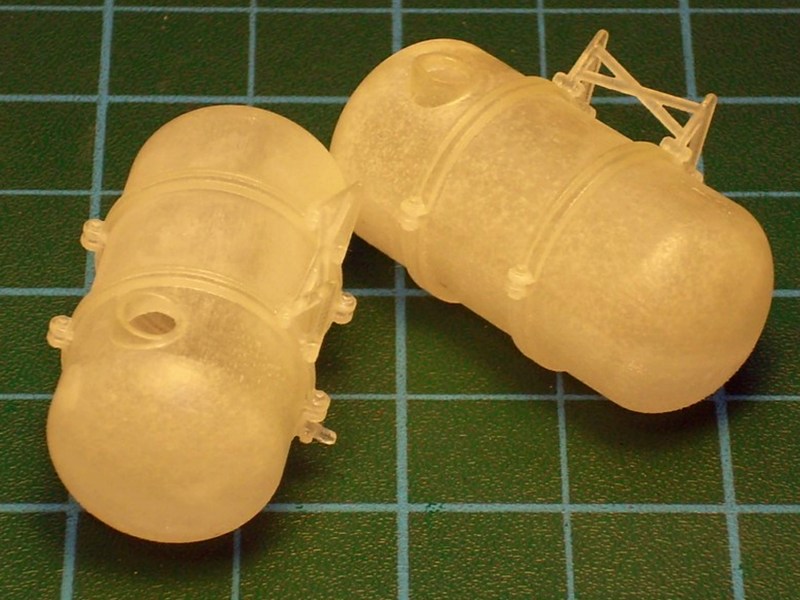
 The two 25 litres cylindrical fuel tanks mounted externally on both sides of the pilot seat, were designed such way to get 3D printed as hollow parts and be presented with lids open to show the interior area. 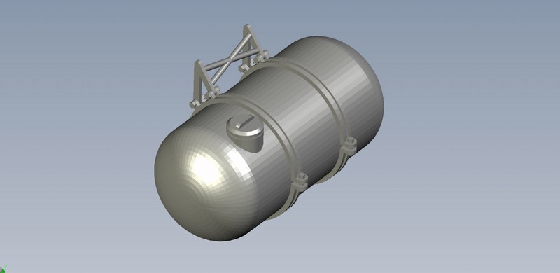
 |
Mesajı Yazan: Nick_Karatzides
Mesaj Tarihi: 10/08/2014 Saat 22:06
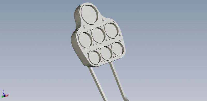
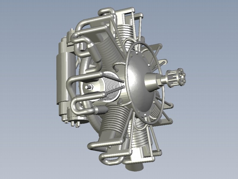
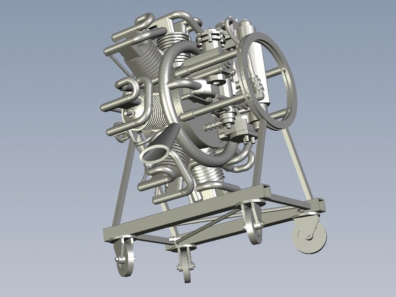
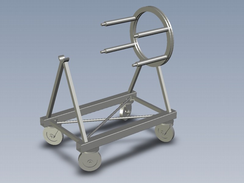
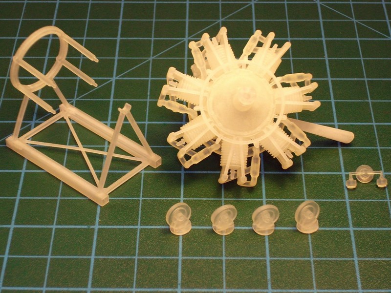
As previously said, I found interesting idea to have the 7-cylinders radial engine would be installed inside the helicopter's belly in the fuselage center-section (and become almost hidden) and also 3D print a second removed engine, place it on a wheeled stand and present it nearby, as it would be there for maintenance purposes. By this way, helicopters inner area and the engine details would be both visible by any angle for the models observer.
 |
Mesajı Yazan: Nick_Karatzides
Mesaj Tarihi: 10/08/2014 Saat 22:24
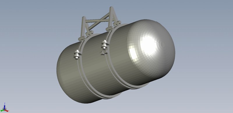
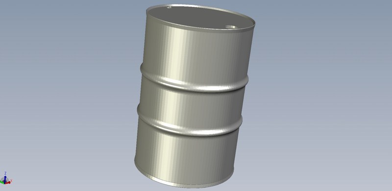
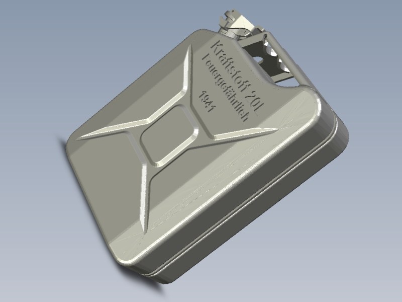
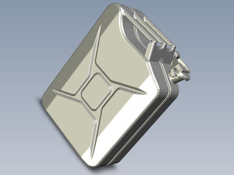
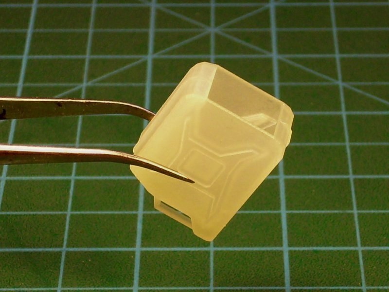
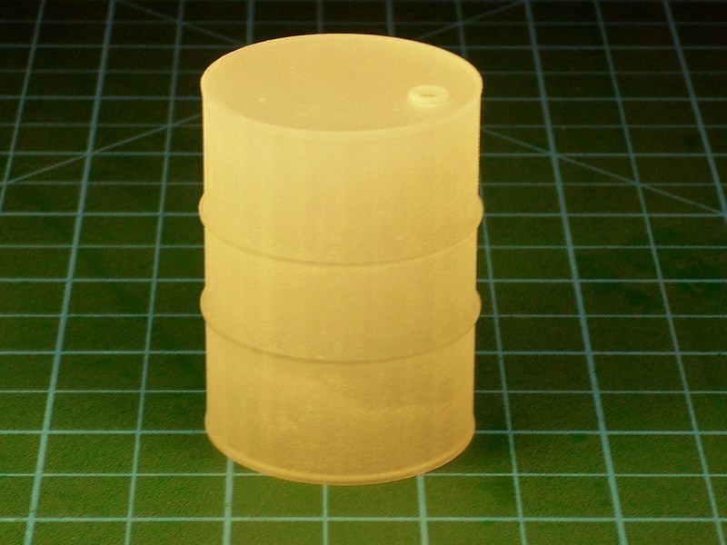
Some additional parts unrelated to the helicopter structure, also designed to get 3D printed later and be used later as part of a diorama scene. For example a couple of 200 litres fuel drums (also known as 55 gallons drums in USA) and few 20 litres (4.4 imp gal; 5.3 US gal) Jerrycan fuel canisters (originally called Wehrmacht einheitskanister) designed in Germany during 1930ies for military use. These fuel drums & canisters used by Wehrmacht, Luftwaffe & Kriegsmarine during WWII had the Kraftstoff 200L Feuergefährlich Luftwaffe and the Kraftstoff 20 L Feuergefährlich 1941 inscriptions, engraved or embossed on side. Actually it took only 15 minutes of CAD work on my laptop to have this result under 1/18 scale. As previously described, the CAD file can be easily scaled up or down to reach the desired dimensions, with few mouse clicks only and later be 3D printed under any scale. Yes, I could scratchbuild some WWII Wermacht style fuel drums or canisters with my own hands, using metal foil or by vaccumforming styrene sheet, or simply by solid epoxy putty, but it would take much more time and I would surely get some dirt under my nails. The easier, the better! Actually, Im not really sure if the handmade result would be so accurate in scale or if I could possibly build it within few minutes only. Notice that the fuel drum & canisters are not solid - they were CAD designed such way (width of skin is about 0.3 to 0.4 mm), aiming both to represent as closely as possible to real ones and also could be later filled with transparent resin material to simulate liquid fuel, always visible through the opened filler cap.
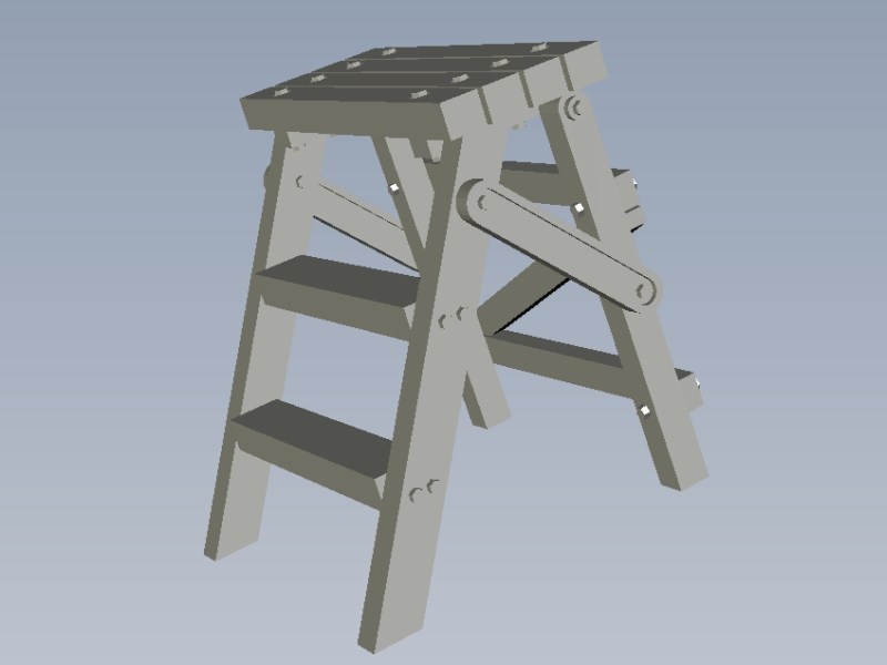
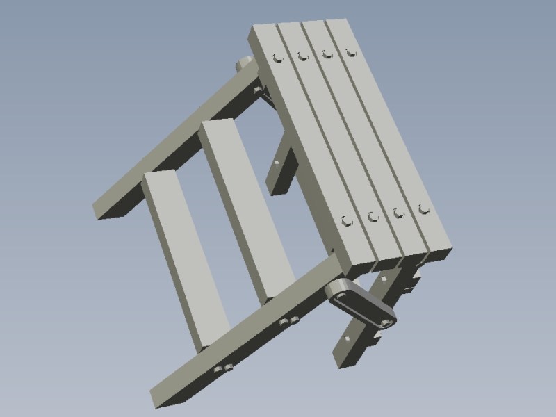
 At last, a final piece also 3D designed to be used as a wooden 3-steps ladder as used by Luftwaffe WWII ground crews and technician personnel for ground vehicle & aircraft maintenance procedures. 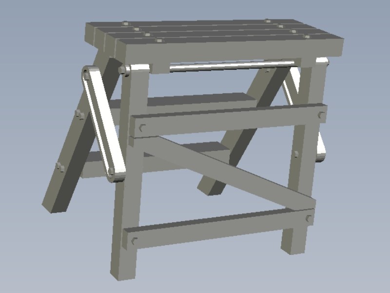
 |
Mesajı Yazan: Nick_Karatzides
Mesaj Tarihi: 10/08/2014 Saat 22:34
|
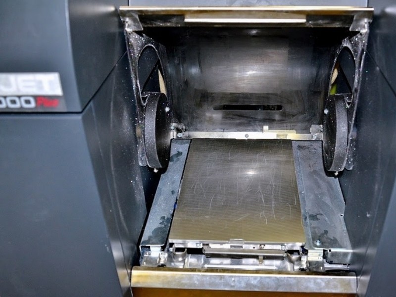
After digitally building the Fl-282 Kolibri 3D model using only mouse clicks, I saved it as an STL - STereoLithography format binary file and forward it on the 3D replicator to start generating the individual parts of the actual scale model. To do so, I used the best available tools & plastic material and asked from Shapeways, a special digital fabrication lab equipped with a high-precision & high-cost ProJet HD 3000 machine for creating custom made-to-order products, to 3D print it. The 3D printing material used was a special plastic called VisiJet SR 200, a UV light cured acrylic polymer plastic material for 3D printing with ± 0.025 mm accuracy for every 25.40 mm. Its actually an organic mixture, consists of 55% triethylene glycol dimethacrylate ester and 45% urethane acrylate polymer. It is printed using the MJM aka Multi Jet Modeling process. During this MJM process, cartridges of acrylate and/or wax material are heated and the plastic material is fired in ballistic micro droplets from a multi-chambered print head containing hundreds of Piezo jets. Molten plastic is deposited onto an aluminum build platform in layers using several nozzles, essentially like a large print that sweeps across the build layer. As the heated material jets onto the build plate, it solidifies instantly. After each layer is deposited, it is cured & polymerized by a wide area UV lamp. The next layer then applied, and through this repeated process layers of thermoplastic build up into a model. This method can print durable plastic parts with a high level of detail and accuracy as well as burnout materials and real wax parts for casting. Layers can be as thin as 16 microns, so MJM produces fantastic surface finish with minimal stepping.
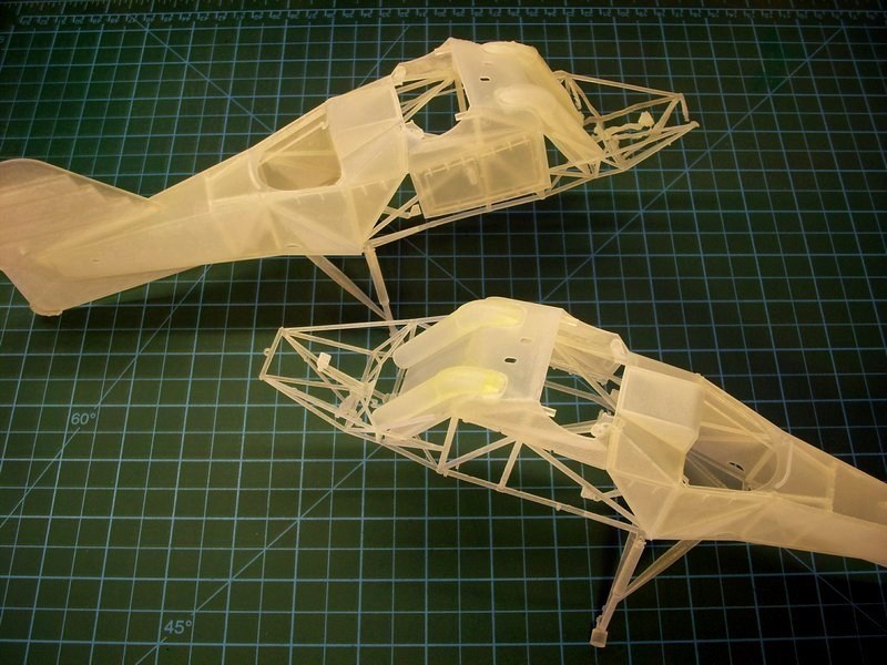
The 1/18 scale Fl-282 V21 Kolibri full fuselage model kit consists of 60 different 3D printed parts made of matte translucent plastic material - in fact, the kit parts are quite more, but smaller in size are interconnected on same sprue frame which is counted as one part. Kit was CAD designed and 3D produced in such way to simplify assembling process while maintaining necessary details required by the scale size. Following the instructions described into the 102-page ultra-detailed http://www.pdf-archive.com/2015/11/14/1-18-scale-flettner-fl-282-v21-kolibri-instructions/1-18-scale-flettner-fl-282-v21-kolibri-instructions.pdf - 1/18 Fl-282 V21 full-fuselage kit building instructions manual (which can be found http://www.pdf-archive.com/2015/11/14/1-18-scale-flettner-fl-282-v21-kolibri-instructions/1-18-scale-flettner-fl-282-v21-kolibri-instructions.pdf - HERE as a PDF format downloadable file), the assembling process becomes easy. 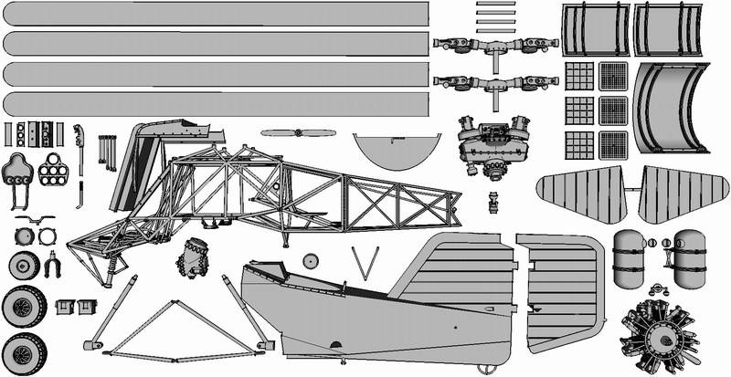
 When printing is finished, the model parts are removed from the tray and placed into an oven that melts away the wax support material. Next, the models are placed into an a ultrasonic oil bath to remove any remaining wax residues, and then a ultrasonic water bath to remove any oil on the model. Final inspection and dry by hand follows for every single model part. Although the ProJet HD 3000 prints in high resolution (16 microns per layer) and can easily produce high detailed parts as small as 0.1 mm, it is better to avoid printing such small parts because they could easily get lost while washed into ultrasonic bath later, for wax residues removing. 
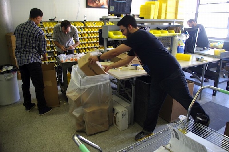
 Keep in mind that due to increased 3D printed items manufacturing demand and workload in Shapeways factory, a complete model kit takes about 5 to 7 days to get produced after order. Depending customers location, the 3D printed parts are produced at one of two Shapeways production lines based at NYC Long Island, USA or Eindhoven, Netherlands and shipped Worldwide, (24hrs to 48hrs delivery time) right at your doorstep by USPS, UPS and DHL with most reasonable prices. 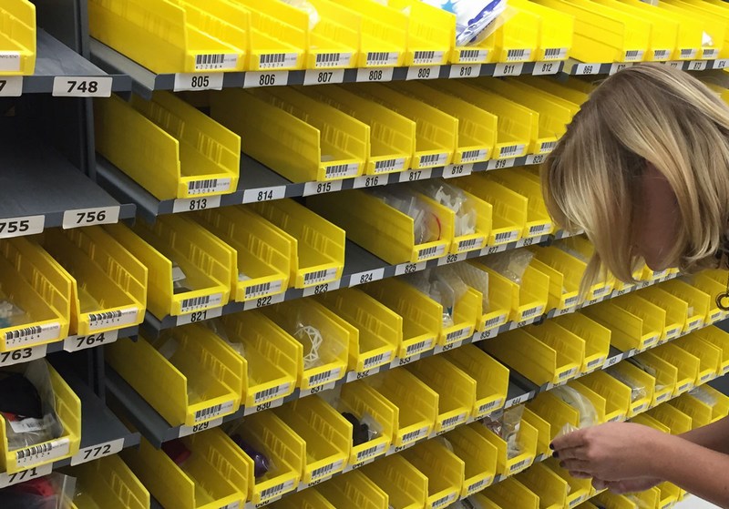
 |
Mesajı Yazan: Nick_Karatzides
Mesaj Tarihi: 10/08/2014 Saat 22:44
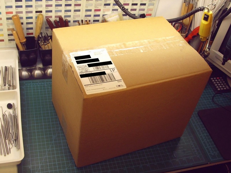
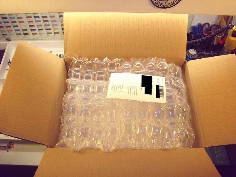
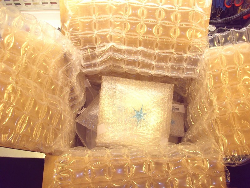
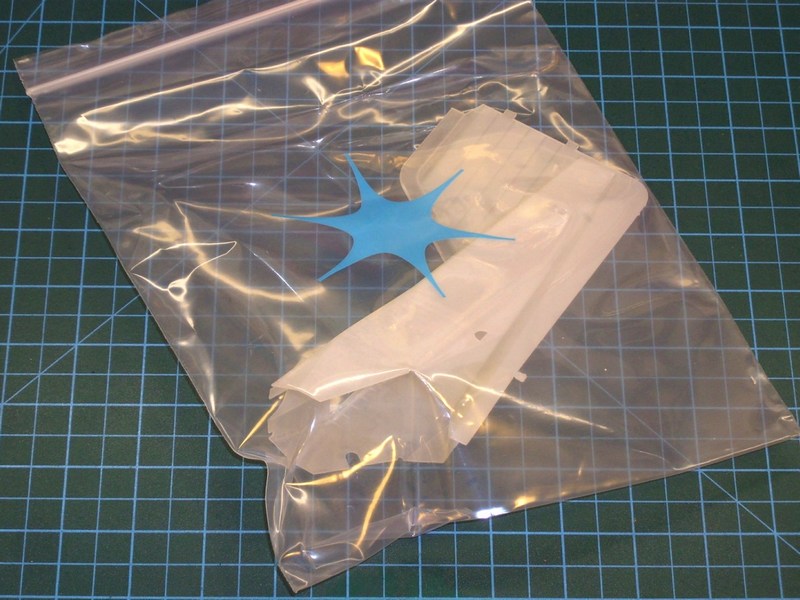
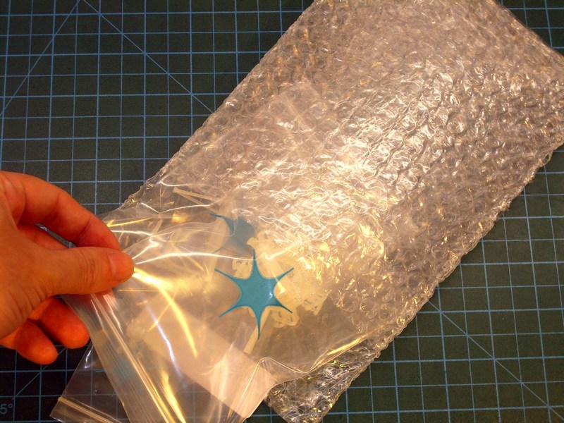
Shortly thereafter, the 3D printing proceeding outcome pleased me while watching the Mbytes, magically converting into actual physical objects. Yeah, thats what I call cool gadgets on a scale modelers service. As soon as 3D printing process completed, the produced parts were cleaned & checked for broken parts or imperfections by Shapeways 3D printing lab specialized personnel. Later, everything carefully packed and shipped to my home address using UPS 24hrs delivery service. Next day, I got home to find a Shapeways box on my doorstep. After a long eye roll from my wife, I quickly grabbed a knife and opened it like all kids open their presents on Christmas morning. Nothing out of the ordinary, I decided to take a few photos to illustrate the experience of receiving my own custom designed & 3D printed model kits package and get in my hands the result of my very own custom-made kit, designed with laptop mouse clicks only and built from zero by converting a CAD binary file into an actual physical object, under my preferable 1/18 scale. Cool stuff, isnt it?

 |
Mesajı Yazan: Nick_Karatzides
Mesaj Tarihi: 10/08/2014 Saat 22:54
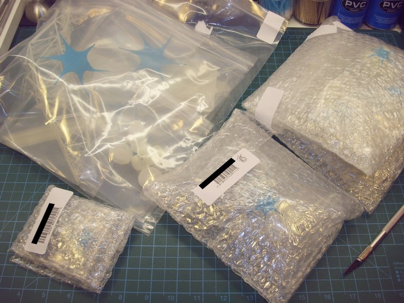
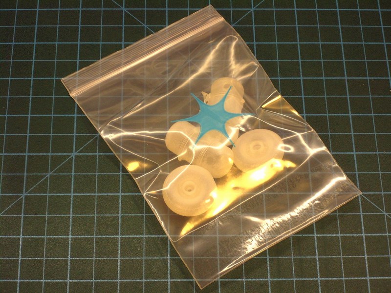
Each one of the two complete custom-made kits consists of 60 different 3D printed parts, some quite big and some others so tiny that could be easily become victims of the carpet monster. The only difference between these two Kriegsmarines V6 and Luftwaffes V21 custom-made complete kits, is that the single seat V6 version kit contains an extra cover for the observers rearwards facing office just behind the rotor shafts. On the other hand, the two-seater V21 version kit extra contains the two cylindrical 25 lt fuel tanks placed on either side of the cockpit, which are absent on V6 naval kit.
 |
Mesajı Yazan: Nick_Karatzides
Mesaj Tarihi: 10/08/2014 Saat 23:11
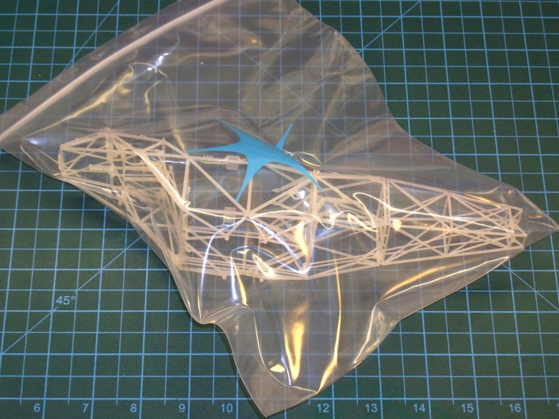
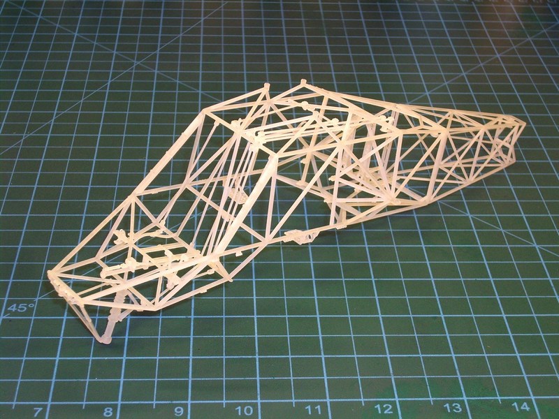
Each complete kit contains the basic frame sections, the elevator & rudder fins, the landing gear wheels, the 7-cylinders radial engine, the upper rotor transmission & gearbox, the rotor heads & rotor blades, the two cylindrical 25 litres fuel tanks (V21 kit only), the cockpit compartment with front & side instrument panel, the control stick with thrust & collective levers & the rudder pedals, both crew seat frames (2nd seat for V21 kit only), a couple of cowling & opened for maintenance hatches and plenty of additional minor details such as supporting rods, control bars, knuckle joints, pulleys, hinges, D-rings etc, etc, etc. Some cable wires & rigging will be later added manually. As said before, any extra diorama accessories visible on some pictures (eg. engine's stand, fuel drums, fire extinguisher, jerrycans, wheel chokes, wooden ladder etc) are not included into kit but is possible to get 3D printed and be purchased separately.
 |
Mesajı Yazan: levburkara
Mesaj Tarihi: 12/08/2014 Saat 04:45
|
I look forward to the next steps. I first came across zenithal lighting while admiring the works of Diego Quijano:
The F-104 article (though by Ricardo Rodriguez, not by Diego) was very informative: http://dqscaleworks.blogspot.com/p/articles.html - http://dqscaleworks.blogspot.com/p/articles.html There is a long discussion of how to best simulate zenithal lighting with colors and shades. I am sure there are tons of other articles elsewhere. In general, Diego's site is full of very attractive models and articles: http://dqscaleworks.blogspot.com - http://dqscaleworks.blogspot.com I am drawn to all the airplane works, but others categories are also mind blowing. You're probably already familiar with these, but wanted to share these as others may also find them useful. I am not sure what I think about that zenithal method though. Like many other things, subtlety is key and I can see why going overboard with that can quickly diminish the attraction. So the Spanish way seems to exaggerate things a little too much for my taste (see the Mig-21 there), and some of these lighting tricks get too pronounced. However, my view is just a matter of taste and opinion and I greatly appreciate the techniques. Will be interesting to see your results. |
Mesajı Yazan: Nick_Karatzides
Mesaj Tarihi: 18/08/2014 Saat 15:00
|
Orjinalini yazan: levburkara Well, I agree that the "Spanish way" seems to exaggerate things and sometimes looks a little too much. But, since we are talking about an artistic approach, I think, that these small artistic excesses emphasize a whole style in our hobby. As final, it may not be 100% accurate to reality, but somehow it looks nice & acceptable by our own eyes - and that is what really matters.
I am not sure what I think about that zenithal method though. Like many other things, subtlety is key and I can see why going overboard with that can quickly diminish the attraction. So the Spanish way seems to exaggerate things a little too much for my taste (see the Mig-21 there), and some of these lighting tricks get too pronounced. Orjinalini yazan: levburkara This Flettner Fl-282 V21 Kolibri helicopter (available in "cutaway" version too) and a Bleriot XI-2 1912 era monoplane model as used by Turkish / Ottoman Army during Balcan Wars period), both designed & produced in huge 1/18 scale, are available for sale as full 3D printed kits, produced on high-precision 3D printers by using best available polymer plastic material to ensure the best printing results & highest possible quality on kit parts. Interested collectors, scale modelers & hobbyists could follow the building process and have a look on Work-In-Progress detailed pictures.
Will be interesting to see your results. Click on http://www.anyuta3d.com - Anyuta 3D printed scale models online catalog to have a look. 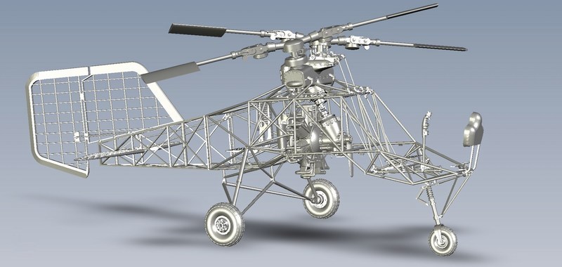
 |
Mesajı Yazan: Nick_Karatzides
Mesaj Tarihi: 01/02/2016 Saat 03:05
|
Its been a long time, more than one year as far as I can remember, since my last update into this forum - not unreasonably as youll find out by reading the following lines. You see, 2015 almost as a whole year, was for me and my family - or at least what is left of it - a very bad year. Life is full of surprises and reminds us daily that we are only human beings, absolutely vulnerable to almost anything. Life prooves by most cruel way that we can become nothing more than dust and faded memories, at any moment, in just a blink of an eye. The following text and attached photos are about two years old and were supposed to be published on scale model related forums & magazines in late 2014 or early 2015. Unfortunately, we may make our plans but God has the last word and decided to take my angel for a while until well meet again on the other side. I'm not worried - I know she is patiently waiting for me to join her some day and I pray for this day to come soon.
Although the above lines are not directly related to a hobby forum, sharing my thoughts with fellow scale modelers, relieves pain and makes grief a little softer. However, I would greatly appreciate if public comments & responses will be exclusively focused on scale modeling matters.  |
Mesajı Yazan: Nick_Karatzides
Mesaj Tarihi: 01/02/2016 Saat 03:47
When I first got this 3D printed kit in my hands, I noticed that most of the kit parts had slight traces of oil on their surface, so each time I touched the parts, my fingertips become oily. What really happened? Obviously, after the 3D printing process was finished and the kit parts been removed from the printer tray to be washed into an ultrasonic oil bath and later an ultrasonic water bath, some oil traces escaped the clean inspection and dry by hand procedure. When I later examined all parts by touching one by one with bare hands, I accidentally transferred the oil traces to every single part. When I realized it, it was already late. Well, it was not exactly a doomsday, but the kit parts should be cleaned thoroughly, because even the slightest trace of oil on the surface of model, could potentially be a problem in the painting process. Simplicity makes things flow without effort and oil traces could easily be completely removed by sinking everything into a 2 litres plastic bowl filled with White Spirit and leave it there for few minutes to wash oil traces. Shortly after all kit parts enjoyed their bath into a White Spirit filled bowl, they were washed with liquid soap and warm water and placed on soft paper towels and allowed to dry.
 After all kit parts washed in White Spirit & water to clean the oil traces, every section of the model has been repeatedly dry fit tested to ensure that all individual parts could be later combined together as an overall built model. When looked OK to me, each part sprayed over with Ammo Mig Jimenez AMIG2004 White waterborne polymer primer to spot mistakes and prepare for paintjob. The next day, I did a visual inspection and shot some pictures. It looks that overall white primer, really helped to visually pop-up the printed detail and proved that use of best available 3D printing material resulted smooth and glossy surfaces on kit parts. As always, the final check held by my sweetheart wife who conducted a strict quality control and 3D printing result evaluation. With persistence on detail, she examined each one of the kit parts and compared them with the CAD design on computer screen. In fact, she spotted an almost undetectable tiny crack on a frame rib inside the helicopter fuselage, which had escaped my visual inspection earlier. Once the process complete, she smiled & proudly signaled green light for further building. 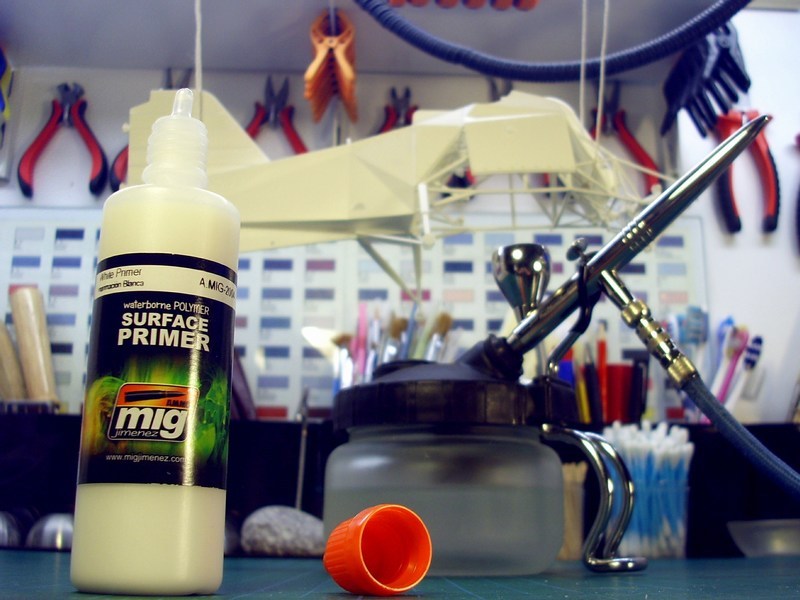
 |
Mesajı Yazan: Nick_Karatzides
Mesaj Tarihi: 01/02/2016 Saat 03:55
|
As soon as the parts were already cleaned & dry fit tested, it was about time to start assembling everything as one model. I usually follow two simple rules while attempting to assemble kit parts and later paint a model: - Paint the individual parts first and assemble the scale model later or - Assemble all individual parts first and paint the overall built model later. First option seems as more appropriate - it would surely make my life easier to paint individual parts first and assemble all together later. As already wrote into previous paragraphs, the model was 3D designed in such a way so as to avoid creating gaps between the parts to be later assembled. Notice that, no filler putty used and no sanding done throughout the whole process! Most of the kit parts, such as the tail rudder & horizontal stabilizer fins, the pilots & observers seats, the main & nose landing gear wheels, the cylindrical fuel tanks, the upper gearbox and of course the rotor blades will separately paint, weathered and later be attached on models overall structure using CA superglue, which does bonds in only few seconds, reaches extremely strength at room temperature and it is suitable for materials such as wood, rubber, plastic, metal, ceramics, leather, marble, polyethylene, polypropylene, teflon etc. On the other hand, there were few tiny parts such as some hinges & D-rings on main fuselage and gearbox complex that had to be assembled before painting process start. |
Mesajı Yazan: Nick_Karatzides
Mesaj Tarihi: 01/02/2016 Saat 04:16
|
Before dealing with this project, I had the (false) impression that Kolibri helicopters were all same - at least identical. After all, only 24 were produced. Once again I was wrong. Study & research on available printed material, 3view diagrams, photographs and videos actually reveals that there were plenty of differences between them - obvious differences or just small details identified after careful observation. In some cases, the exact same helicopter (for example the V12 with registration CJ-SF) was appeared once to be painted with Kriegsmarines medium grey camo (click https://s25.postimg.cc/vtc9lzw9r/IMAGE_0032.jpg - HERE ) and later with Luftwaffes dark green colours (click https://s25.postimg.cc/80278j76n/IMAGE_0048.jpg - HERE ) or even once having the flat plexiglass panels around the cockpit installed and latter simply missing them. On the other hand, the two-seater Fl-282 V21 helicopter registered as CI-TU, maybe the most famous of the Kolibris, was quite unique. In following picture, dressed up with Luftwaffes TransportStaffel TS40 colours, as appeared at Ainring AB at Mühldorf, Bavaria, in its operational role as artillery spotter, back in 1944 to 1945 days. 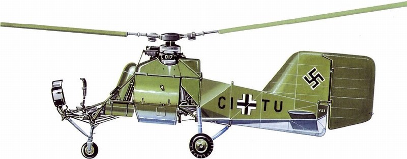 |
Mesajı Yazan: Nick_Karatzides
Mesaj Tarihi: 01/02/2016 Saat 04:48
|
To recreate the Fl-282s Luftwaffe camo paint, I did use the Life Colors Gerrman WWII Luftwaffe set #1 6-pack set, of 22 ml bottles.
- Life Color UA501 RLM 70 Schwarzgrün / Black Grey acrylic paint, - Life Color UA502 RLM 71 Dunkelgrün / Dark Green acrylic paint, - Life Color UA503 RLM 65 Hellblau / Light Blue acrylic paint, - Life Color UA504 RLM 02 Grau / Grey acrylic paint, - Life Color UA505 RLM 79 Sandgelb II / Sand Gold II acrylic paint and - Life Color UA506 RLM 80 Olivgrün / Olive Green acrylic paint. 
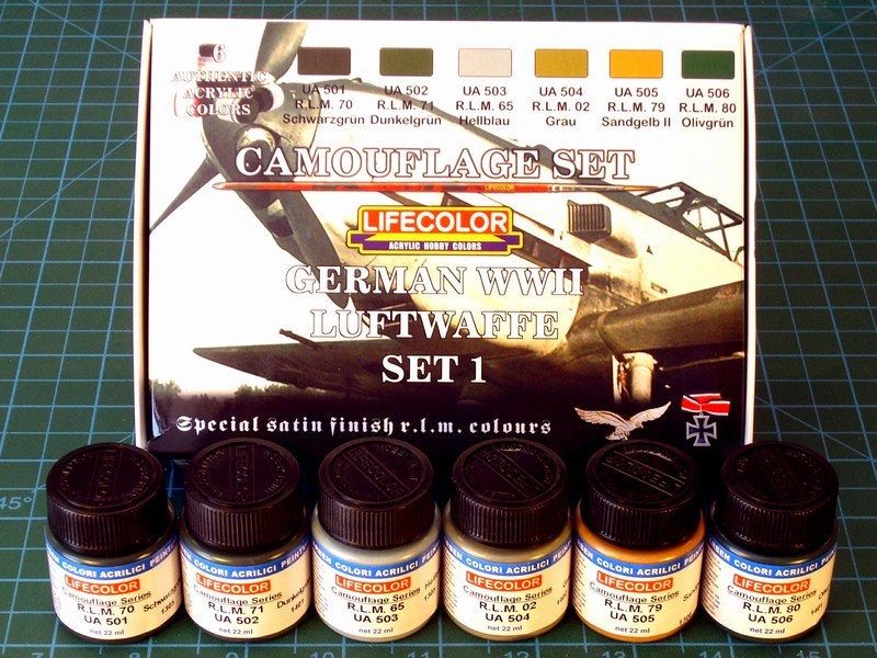 To be more specific, the basic colours applied on model according WWII Luftwaffe ReichsLuftfahrtMinisterium designations are the RLM 71 Dunkelgrün FS 34079 & RLM 65 Hellblau FS 26329 paints. 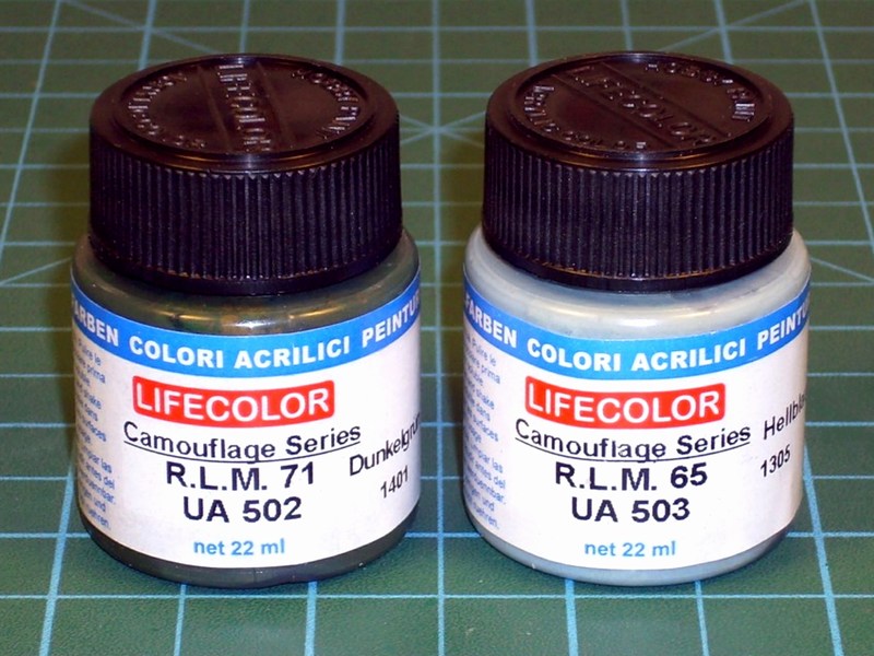 |
Mesajı Yazan: Nick_Karatzides
Mesaj Tarihi: 01/02/2016 Saat 13:08
|
Pre-shading by airbrushing dark coloured lines on model before the basic paint is a method followed by many modelers the last few years. To be honest, I never liked it, never really understood the reason to do something like that and yes, I admit that I never had some decent results whenever I tried it. IMHO adding pre-shading lines before painting is a time wasting & useless procedure with no artistic results on model. After all, whats the reason to try this, if (one way or another) additional paint layers will be applied on model later, to enlight or darken the basic paint? Anyway, I mostly prefer to:
- Directly apply the basic paint (without pre-shading and other time wasting nonsense) and later add some colour shades by enlightening or darkening on specific areas or - Follow the Francois Verlindens old-fashioned way by airbrushing a very dark colour (usually some black & dark brown mixture) all around the model until fully cover it and later gradually light-up the models surfaces by repeatedly applying very thin layers of basic paint. The abovementioned Francois Verlindens way possibly practiced by other painters & hobbyists decades before, was first introduced as a painting technique for scale modelling by Francois Verlinden, more than 25 years before. Back in the late 1980ies days, when the internet was not known yet and modelers only available reference was the (usually expensive) books from local hobby shop, a Belgian artist named Francois Verlinden managed to create 3D-alike light effects on flat surfaces. He did that by repeatedly airbrushing very thin layers of basic paint on a black (or dark brown) undercoat and then gradually lighten the dark surfaces to replicate the way that sunlight hits on large objects. Since then, some new painting tricks appeared and many modelers improved some older (and forgotten) techniques and re-introduced them as their own new inventions. During the last few years, the Francois Verlindens old-fashioned way was re-introduced and become popular around the scale modelling community (especially among armour painters), by its new name: Modulation! IMHO this modulation fashion looks nice on models but the results are not so strictly realistic comparing to the real world objects. As scale modelers, we always have to balance between realism factor and artistic expression. Yes, I admit that modulation effect does not accurately replicate the reality, but it looks so artistically attractive and becomes easily accepted by our visual subconscious. 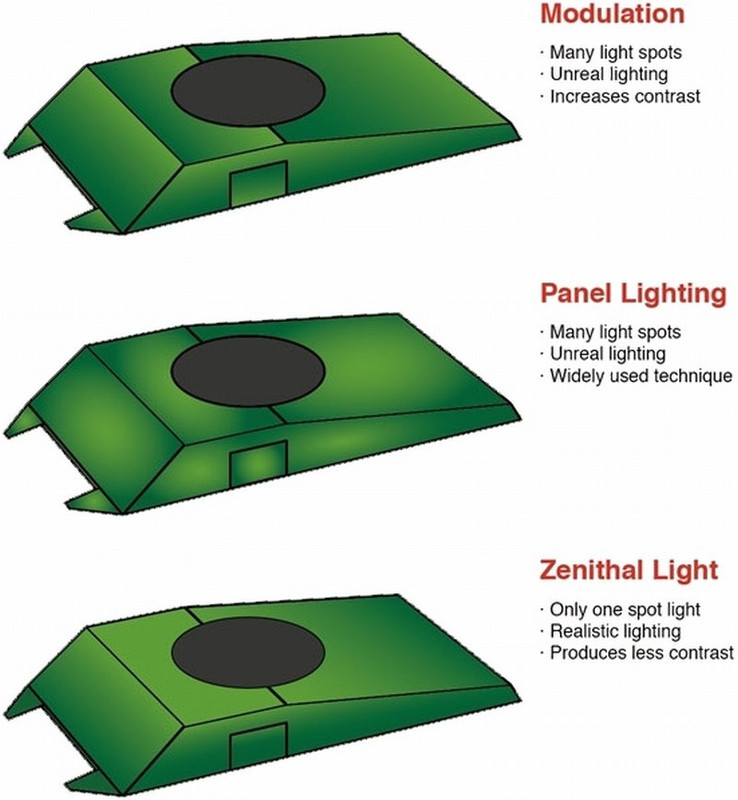
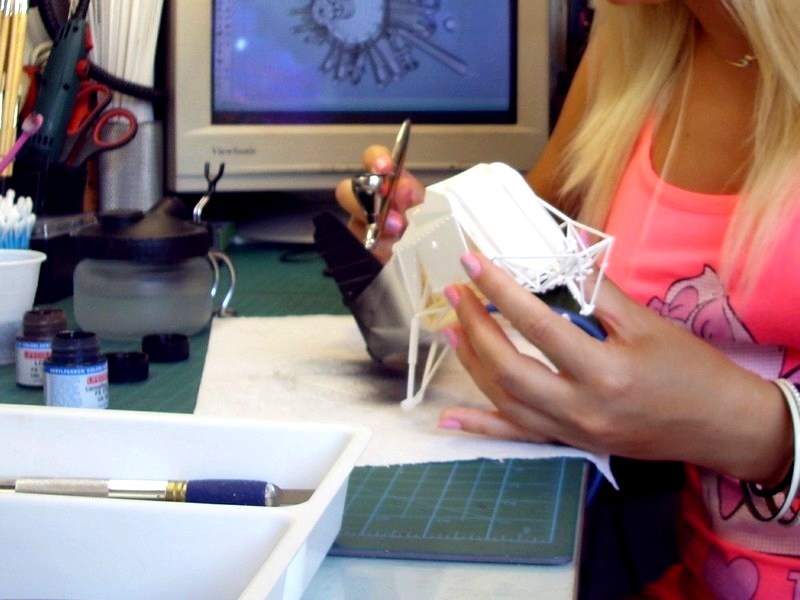
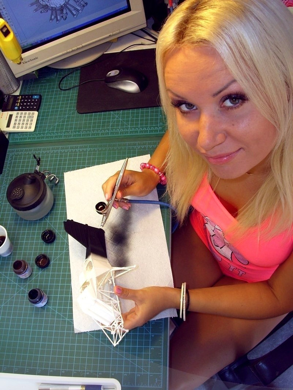
 Process started, by airbrushing an overall undercoat mixture of 80% Life Color LC02 Matt Black and 20% Life Color LC37 Matt Burnt Umber acrylic, to prepare the flat surfaces for the basic paint which about to follow. Asking a blonde to paint it black could be confusing for a moment and result some priceless answers. 
 |
Mesajı Yazan: Nick_Karatzides
Mesaj Tarihi: 01/02/2016 Saat 13:09
|
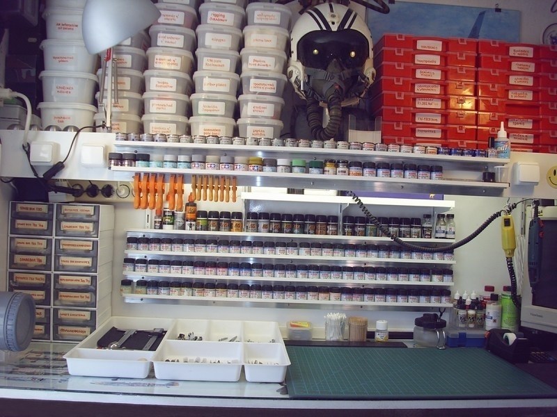
Having succeeded (in her first airbrushing attempt) to spray black paint onto my clean & tidy hobby bench, I realized that it was time to urgently have a new spray booth for her, considering that my old one broke down after almost 15+ years of use. My initial thought to buy a brand new one, quickly dismissed when I found that the cheapest China-made spraybooth was quite small for my big-sized scale models and the purchase price could start from 100 and rise up to 500 or more. Additionaly, due to limited space on my hobby bench and the fact that I usually build big (close to huge) scale models, the spraybooth should be large enough to fit models inside, portable to keep clear the working bench when not in use and should be easily (and fast too) disassembled and stored under the bench.
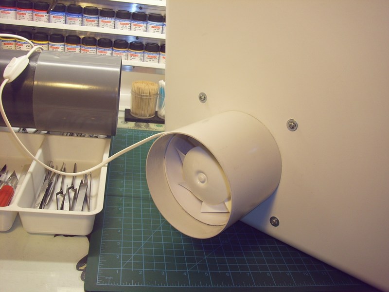
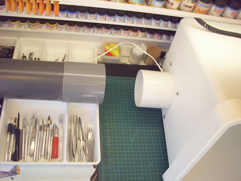
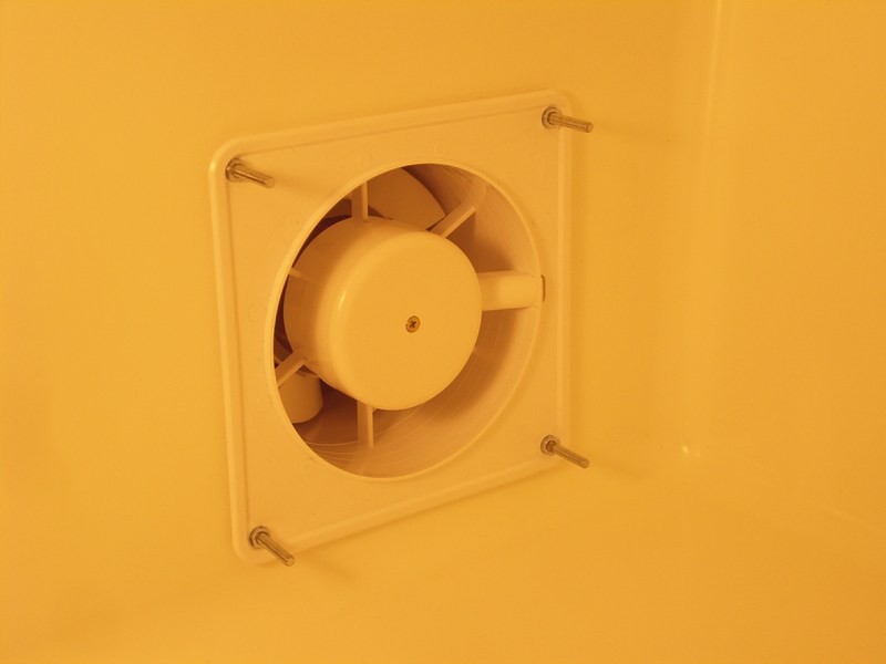
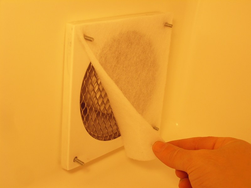
Well, as a good friend once said, everything starts with a wish and inspiration can be found everywhere. I found the following item named http://www.ikea.com/gb/en/catalog/products/70255899 - Sortera which supposed to be a recycling bin with lid or something, at my local http://www.ikea.com - IKEA store. Looking exactly like what Ive been searching for and considering the low 15 price, I bought this 60 litres plastic box (IKEA product code is 702.558.99) and turned it into a paint chamber. Later, I also visited my local http://www.leroymerlin.com - Leroy Merlin home depot (located right next to the aforementioned http://www.ikea.com - IKEA ) store, trying to find the right parts for the project, such as bathroom ventilating fans, outflow plastic tubes and electric wiring. I found two 125 mm diameter bathroom ventilator fans rated at 32 W, 10 dB, 150 m3/h each for only 11 each. The purchase cost for buying materials to build the DIY spraybooth was: - 2 x ventilators rated at 32 W, 10 dB, 150 m3/h each: 2 x 11 = 22 EUR, - 1 x paint chamber (Sortera recycling bin with lid from IKEA): 15 EUR, - 2 x PVC 125 mm Ø plastic tube 90° fittings & bezel parts: 3 EUR, - 1 x PVC 125 mm Ø plastic tube 50 cm long: 1 EUR, - 1 x common kitchen extractor hood filter: 1 EUR, - 1 x electric wiring 2 m long & switch: 2 EUR. The total ammount with all the hardware was 44 (approx $48).  As soon as returned back home, I spent nearly one hour to assemble parts and make the scratchbuilt spraybooth fully functional. The first ventilator slided through the tubular wall opening (already existed for the previous broken spraybooth outflowing), secured in place and got wired to 220 V with a switch. The exterior wall opening is covered with louvers that automatically close when the ventilator fans are turned off, to prevent ingress of cold air in the room during the winter. Furthermore, when spraybooth is not in use, the inner wall opening is manually sealed with a proper cap. 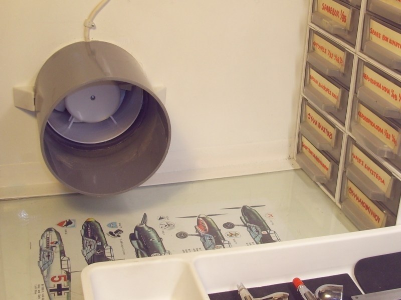
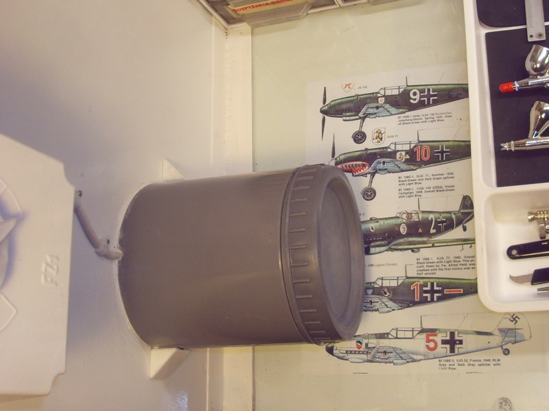
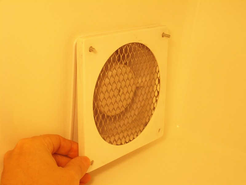
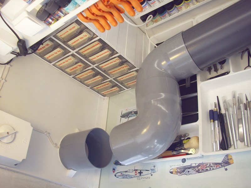 Later, the second ventilator mounted on a 125 mm wide drilled hole on plastic paint chamber side and connected to 220 V with seperate wire & switch. Between the two in-line-mounted ventilators (one located at the beginning and the other at the end of suction flow), a portable S-shaped 125 mm diameter tubing of total length 75 cm is inserted. At last, a common kitchen extractor hood filter installed, to prevent paint particulates entering into the airflow circuit. 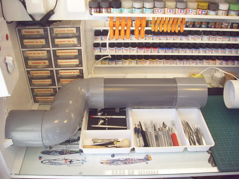
 |
Mesajı Yazan: Nick_Karatzides
Mesaj Tarihi: 01/02/2016 Saat 13:10
As I later found out when first tested the spraybooth, the ventilators proved more powerful than expected, producing a suction flow of total 300 m3/h, meaning that (if my calculations are correct) the air inside the 60 litres paint chamber is renewed every 0.72 seconds. During the first airbrushing test, I noticed that the spray beam got warped (!!!) close to 90 degrees angle, towards ventilation fan and therefore I placed additional filters to reduce the airflow power.
 Long story short? My scratchbuilt spraybooth: - Cost me 44 EUR (approx $48 USD) to buy the hardware, plus one hour work to assemble parts & install electric wiring, - It has a 60 liters (measures 55x45x39 cm) paint chamber able to accommodate big-sized scale models, - It is almost operating silently, not exceeding 20 dB when both ventilator fans are in use, - It is fully portable (can be assembled or disassembled in less than 10 seconds) and - It sucks air like an inverted hurricane, even when filters are installed! 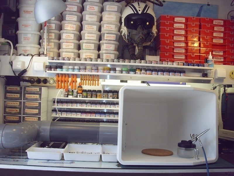
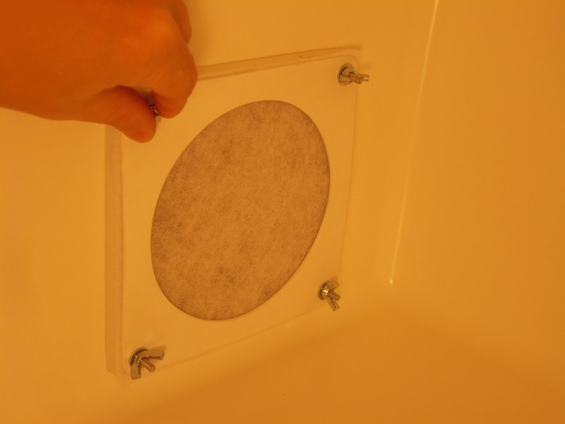
 Having now a new fully functional & custom-made spraybooth, lets return back to to the painting process: All the 60 parts of the model kit, placed onto toothpicks for better handling while airbrushed and sprayed over with an overall mixture of 80% Life Color LC02 Matt Black and 20% Life Color LC37 Matt Burnt Umber acrylic as a primer, to prepare for the later paint layers. The toothpicks pinned onto cork sheet and parts allowed to dry. 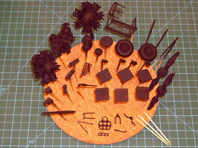 Behold the spraybooth filter, after 30 minutes of continuous black paint airbrushing into paint chamber. The use of this simple kitchen extractor hood filter kept the system clean. Double (or even triple) filter layer would be a good idea to reduce the airflow power in order not to warp the airbrush spraying beam (as previously described) and could ensure that components will remain spotless clean for a long time. If there was no filter at all, dirt & paint particulates would easily enter into the airflow circuit and stick onto the ventilator fans and the plastic tube inner walls. 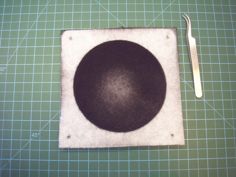 |
Mesajı Yazan: Nick_Karatzides
Mesaj Tarihi: 02/02/2016 Saat 12:00
The goal of modulation technique is to artificially enhance the model so the viewer sees more than what is really there. This is nothing new to us; figure modelers and 2D illustrators have been using this idea for years. Verlinden-era dry-brushing and even current post-shading trends dance around this same idea. To break it down even further, the fundamental theory of modulation effect is based upon using a singular light source, and the level to which you take this idea is inherently flexible. One of the beauties of the technique is that you can add a little, or a lot of it to your model.
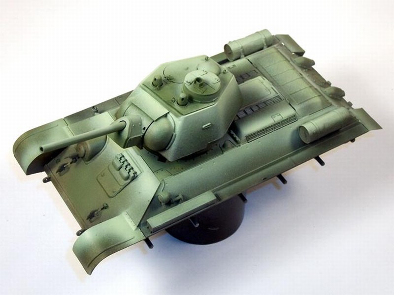
 Modulations effect requires three main levels of color (light, medium and dark) to achieve proper gradations between the values, which are broken into stages as you lighten each progressive step. To do so, lot of airbrushing is required to add some just a little paint layer every time. First, I had to choose a source from which the lighter areas originate. I decide to keep it very simple and intend to have the light coming from the center upper frontal area of the helicopter and will also work well with the downward slope of the top areas. The basic processes and techniques involved are designed to enhance the 3D volumes and details of a model by playing up the balance between dark VS light, shadow VS highlights and so forth. Executing this goal is accomplished primarily with an airbrush by applying gradations of color to give the model more depth. Use of masking paint is essential, in order to focus the airbrush lighter colours spraying onto specific areas only. 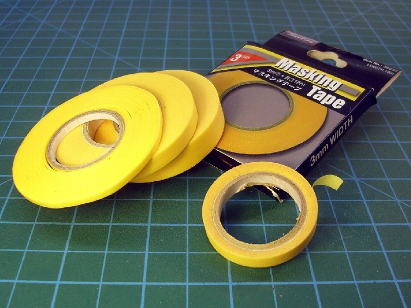 Because of the subject itself, the model is predetermined to have a base coat of dark green. Thus the first layer of color I apply is a coat of very thin Life Color UA502 Dark Green acrylic paint layer, very diluted with Life Colors acrylic thinner in a 30% paint to 70% thinner ratio. The darkest recesses sprayed first, gradually working my way up to the lighter upper surfaces. You can already see the intentional spray pattern developing from the darker lower right to the lighter upper left areas. I will maintain this pattern throughout the entire painting process to preserve continuity with the light source. 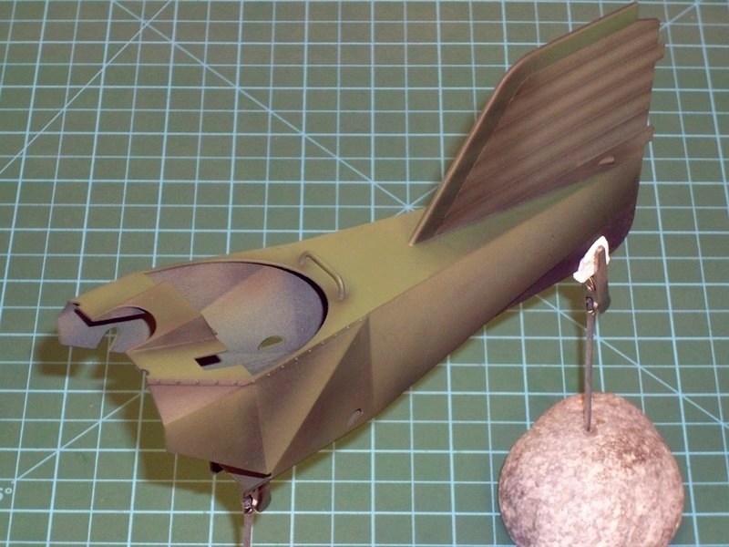
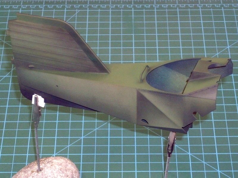 The subsequent spraying sessions will continue to utilize very thin Life Color UA502 Dark Green acrylic paint layers as a base to varying degrees because it is the source of the dark green. I will gradually lighten the model with each successive layer as the modulation painting process continues, so the second layer of Life Color UA502 Dark Green acrylic paint as the medium layer of the base coat, is based upon a less diluted 50% paint to 50% thinner ratio. Note that the darker lower areas receive less paint as the shades are carefully blended together, as seen above. Then, I add just a few drops of Life Color UA081 Sand Yellow FS30257 acrylic paint into the mixture to lighten up this stage of paint application, being very careful to always follow the established gradation pattern. The contrast between light and dark is now starting to become more apparent here. 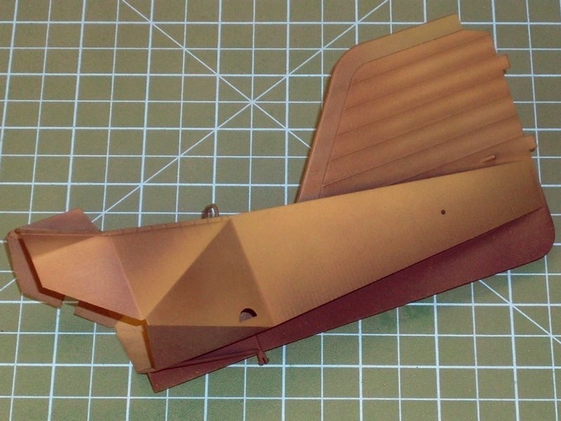 Following same painting procedures, all additional kit parts got some basic Life Color UA502 Dark Green and Life Color UA503 Light Blue acrylic paint and then gradually lighten up or became darker as required. As usual, painted parts placed onto toothpicks for better handling during airbrushing and later pinned onto cork sheet while allowed to dry overnight. 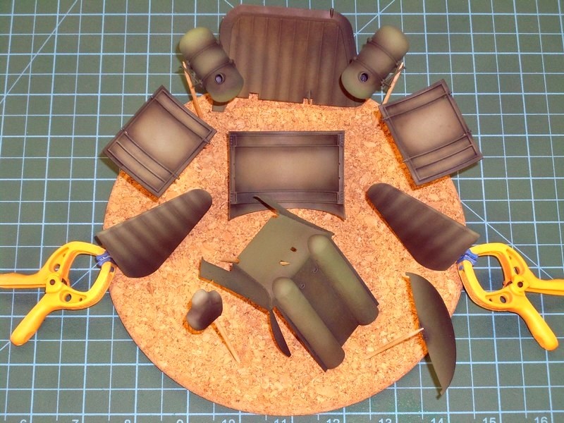 |
Mesajı Yazan: Nick_Karatzides
Mesaj Tarihi: 05/02/2016 Saat 17:30
|
Most of the FL-282 related WWII era pictures reveal that the fuselage truss-type welded steel tube frame on the Kriegsmarines early helicopters was painted light grey colour, following the general idea of the RLM 63 Light Bluegrey on fuselage fabric cover. On the other hand, the Luftwaffes Kolibris seem to had the fuselage steel tube frame painted in some dark colour (RLM 71 Dunkelgrün?) following the doped fabric cover designations. However, it is noticed that few Luftwaffes helicopters were appeared once to have the fuselage steel tube frame painted with dark green colour and later with light grey or even having a frame which individual tubes were painted in different colors. This might have happened due the fact that the Kriegsmarines helicopters later received by Luftwaffe kept original grey frame colour and just paint the doped fabric cover only or because the damaged helicopters were used as a source of spare parts for the remaining Kolibris. A fellow scale modeler from UK, sent me a photograph showing the actual Flettner Fl-282 V20 helicopter frame relic as seen at Midland Air Museum on September 25th 1987, before maintenance crew attempts to restore it into normal condition. Although the helicopters frame looks in bad condition, it is easy to observe that it was painted with at least three or four different colours. Ofcourse, I cannot be sure if this was the actual appearance of Luftwaffes operational helicopters during WWII or if it is a result of poor maintenance, corrosion or even vandalism. Anyway, as long as we accept that the apparently light blue & light grey colours are WWII Luftwafe authentic and not some post-War overpainting job, the picture is a valuable reference source and offers a general view of the paint used on the fuselage & undercarriage frame. 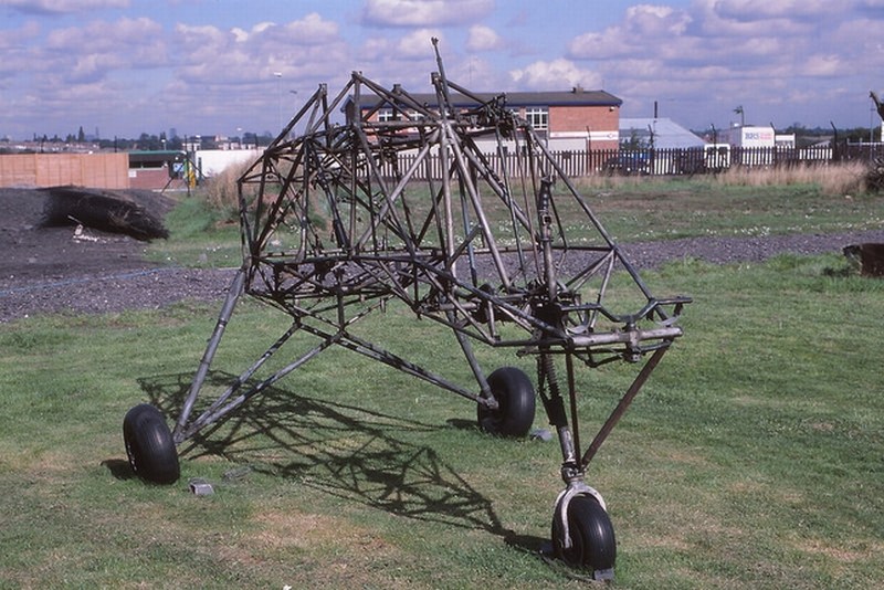 Because of the subject itself, the model is predetermined to have a base coat. Thus the first layer of color I applied was a coat of very thin Life Color UA503 Light Blue acrylic paint layer, very diluted with Life Colors acrylic thinner in a 30% paint to 70% thinner ratio. The darkest recesses sprayed first, gradually working my way up the frame, keeping to the lighter areas on central parts of each tubular part. Same pattern maintained throughout the entire painting process to preserve continuity with the light source and subsequent spraying sessions continued to utilize very thin Life Color UA503 Light Blue acrylic paint layers as a base to varying degrees because it is the source of the light colour. The tubular frame got gradually lighten with each successive layer as the painting process continued, so the second layer of paint as the medium layer of the base coat, is based upon a less diluted 50% paint to 50% thinner ratio. Note that the darker areas receive less paint as the shades are carefully blended together. Then, I added just a few drops of Life Color LC01 Matt White FS37925 acrylic paint into the mixture to lighten up this stage of paint application, being very careful to always follow the established gradation pattern, untill contrast between light and dark started to become apparent. 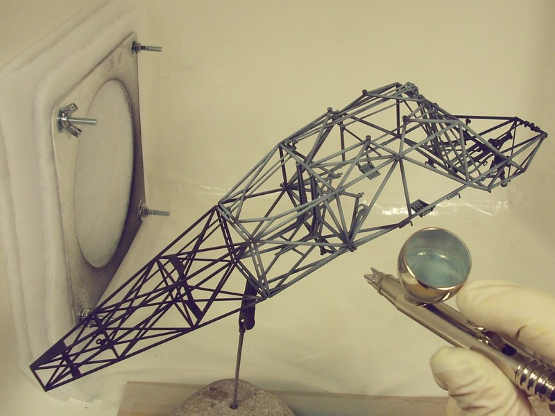
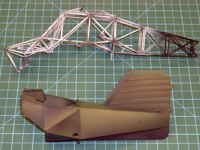 Following same painting procedures, each part (except the parts related to the engine and the drive transmitter) of the kit got some basic Life Color UA503 Light Blue acrylic paint and then gradually lighten up or became darker as required. The kit parts that were supposed to be painted in shades of wood, also got some acrylic base paint. As usual, each part placed onto a toothpick for better handling during airbrushing and later pinned onto cork sheet while allowed to dry overnight. 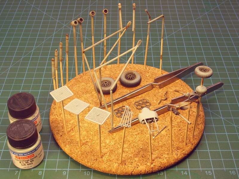 |
Mesajı Yazan: Nick_Karatzides
Mesaj Tarihi: 06/02/2016 Saat 10:54
|
Replicating wood is one of those feared tasks in modeling that many try to avoid at all costs. Having a couple of different methods in mind to simulate wood in scale, but knowing that the following method is much accurate and easier to re-do if something goes wrong, I found good idea to follow some tricks I learned from other builders and changing things that works for me. To simulate the look of rough wood from which was made the helicopters tail section frame, I split the areas to be painted in different categories and sprayed four different primary colors on each area. I used the following colors, which seemed to work OK for me. It is important to use an acrylic base colour because it is chemically impervious to the steps that follow.
- FS31643 available by Life Color as LC21 Matt Flesh Carnicino acrylic paint, - FS30400 available by Life Color as UA084 German Desert Yellow acrylic paint, - FS30257 available by Life Color as UA081 Sand Yellow RLM79VAR acrylic paint and - FS30140 available by Life Color as UA085 US Brown Marrone acrylic paint. 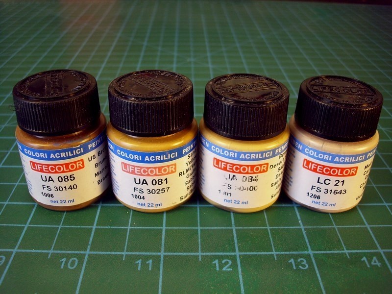 Because the wood composition and quality was not same everywhere, I also use the Life Color's Weathered Wood 6-pack set, of 22 ml bottles and repeatedly covered some areas with different shades of very very very diluted (10% paint to 90% thinner ratio) light layers over the previously applied base colours. To do so, I used the following: - Life Color UA717 Wood Cold light base acrylic paint, - Life Color UA718 Wood Cold light shade acrylic paint, - Life Color UA715 Wood Warm light shade acrylic paint, - Life Color UA716 Wood Warm light shade 2 acrylic paint, - Life Color UA714 Wood Warm light base acrylic paint and - Life Color UA713 Wood Warm dark shade acrylic paint.  I'm not really sure if it is actually vissible into following pictures, but repeatedly applied very diluted & light layers, resulted more natural look of wood shades, without even aplly any oil colours yet. The first applied base colours, are visible under the later applied layers of the Weathered Wood shades, setting a base for the next process. As soon as paint dried, I repeatedly sprayed a very diluted mixture of thinner, Life Color UA717 Wood Cold light base acrylic and Life Color UA716 Wood Warm light shade 2 acrylic at a ratio of 90% to 5% to 5%, over selected areas such as the leading edges and a few other points, that should look more enlightened. 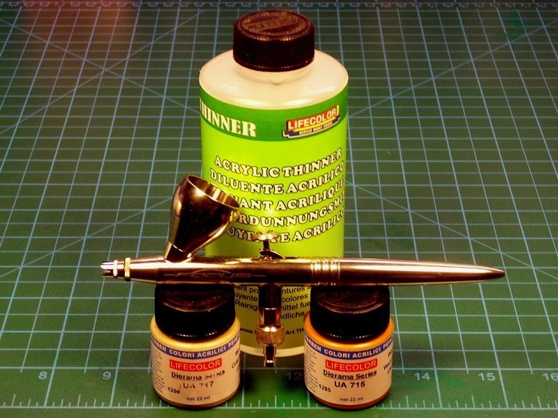 To apply the wood grain on wide areas covered with plywood, I used wood grain colour from artists oil paints. The higher quality artists grade paints work much better because the pigments are much more finely ground. I believe that 502 Abteilung by MIG Productions, Van Gogh and Talens are good brands. The colour of the background coat and the oils may be varied for different kinds of wood. However, be aware that selecting a good colour combination that gives that natural look is tricky. I recommend experimenting on a test piece first before committing yourself to apply the mixture on your latest wondermodel. I arrived at my blend of Burnt Sienna, Yellow Ochre and Raw Umber in a ratio of 25% to 25% to 50% after trying with Raw Sienna (too red), Yellow Ochre (too orange), and one or two mixed combinations. 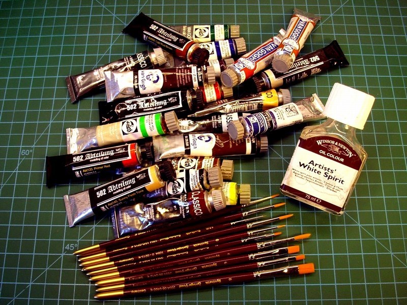
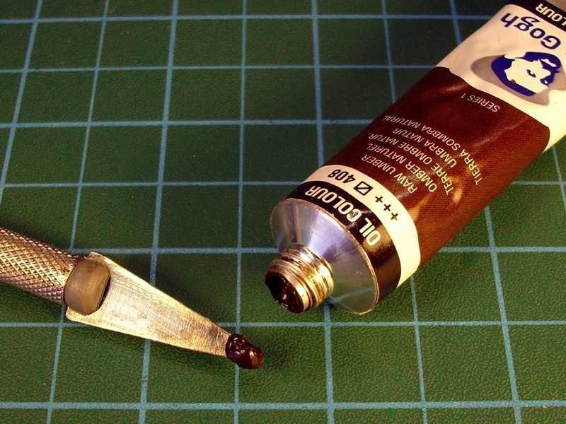
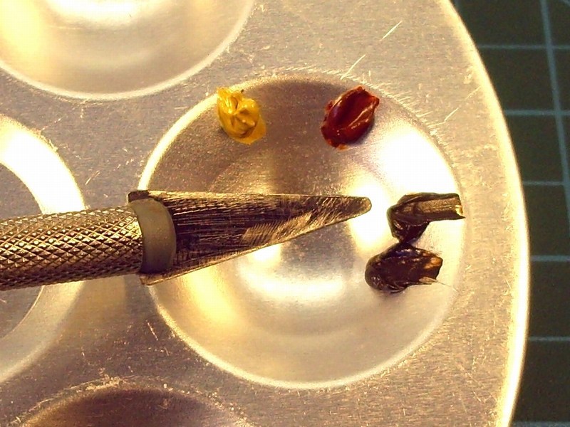 |
Mesajı Yazan: Nick_Karatzides
Mesaj Tarihi: 06/02/2016 Saat 10:54
Once the base coat has cured, I brushed the oils with a broad, soft brush and spread the paint around until the desired colour density is achieved. Because working in oils is a little bit goes a long way, I started by putting just a little bit of paint on the end of the brush. I kept the brush strokes going in one direction and didnt really worry about leaving brush strokes - I wanted them there for the wood grain. I tried not to spread it on too thick, or it would make the next step more difficult.
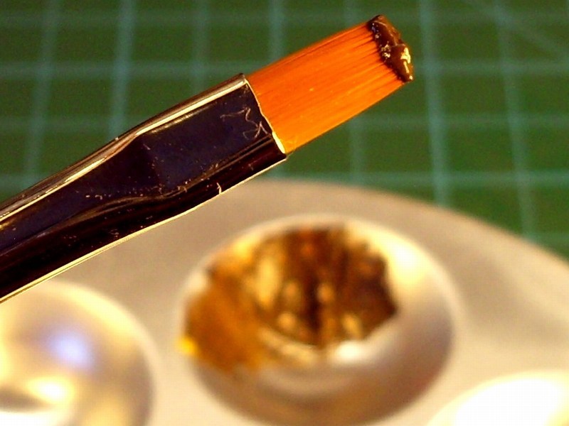 At this point the oils would be workable for several hours. With a broad, soft, clean and completely dry paint brush, I draged over the oil paint, leaving wood grain streaks. I jiggled the brush every now and then to give the grain a bit of variation. As the brush picked up the paint, I wiped it off on a clean, lint free cloth and continue process. Lint free is the key phrase, as any speck of lint would adhere to the oil paint and destroy the finish. The beauty of this technique is that you can clean the oils off and try again if you goof up. Use a clean cloth and paint thinner (mineral spirits or turpenoid - not lacquer thinner) to wipe clean any mistakes and start over again. For the 1/18 scale Kolibri helicopter frame, it took me about two or three tries to get the paint density and colour right, but it really was quite painless. 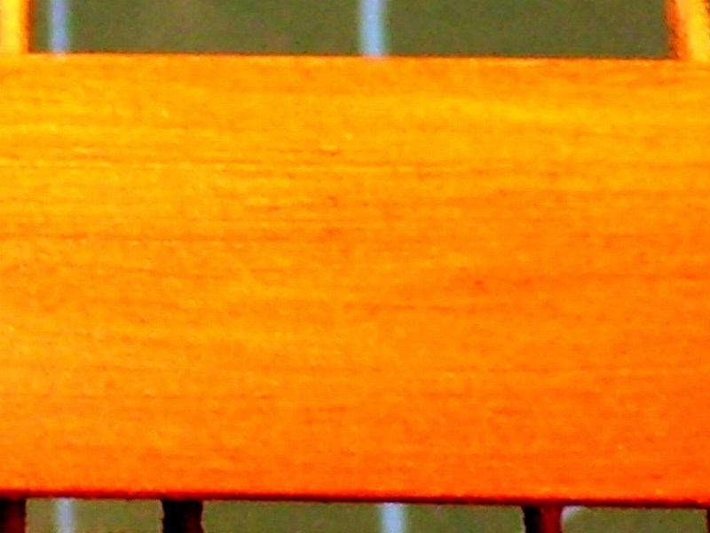 In some parts of the model which should look more bright, I slightly toned up with "Buff" & "Yellow Ochre" mixtures, or even pure Basic Flesh Tone" and Sunny Flesh Tone", while some others had to show darker, using "Brown" or "Raw Umber" color and blend naturally. Meanwhile, I tried same painting procedures on the wooden 3-steps ladder (used by Luftwaffe WWII ground crews and technician personnel for ground vehicle & aircraft maintenance procedures), which also got CAD designed & 3D printed with the helicopter kit parts to be used as a diorama accessory. 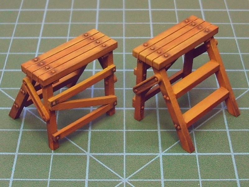 As soon as the result was OK for me, I left it alone to dry for few days and then sprayed over selected areas with Tamiya Color X-24 Clear Yellow acrylic, because it also helps bring the grain color out more. 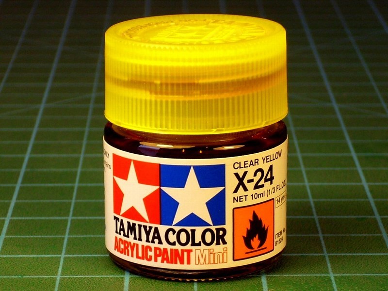
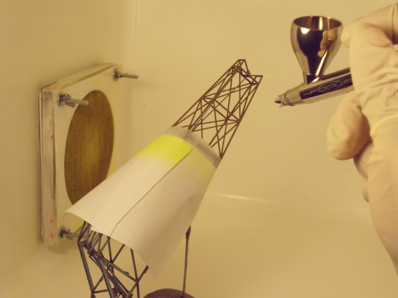
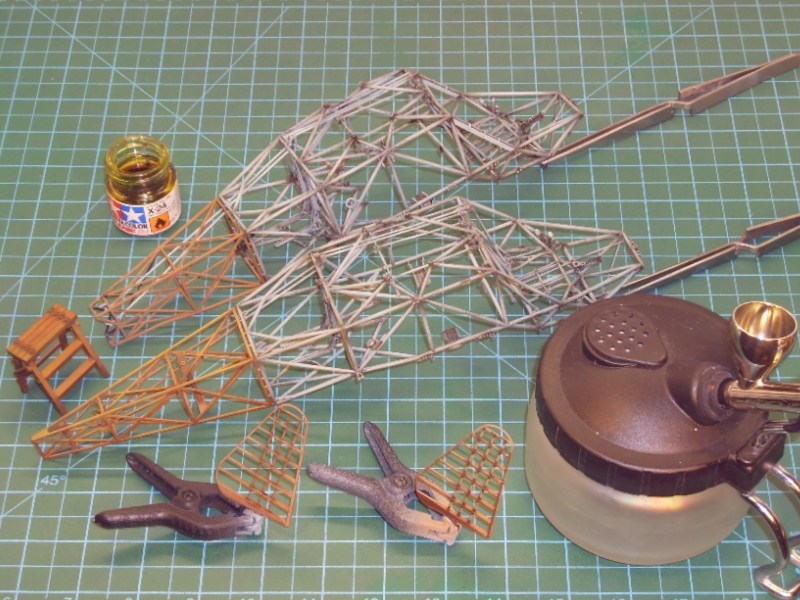 |
Mesajı Yazan: Nick_Karatzides
Mesaj Tarihi: 09/02/2016 Saat 20:23
|
In recent years, most scale model companies avoid (for political correctness reasons) to depict the swastika symbol on kit box and the water slide decal film. In addition, some scale modelers fear of some mighty Holly Inquisitorial Court and remove or misquote the swastika symbol from their plastic aircraft models when present them on exhibitions, contests, magazine articles and hobby related forums around the internet. Since I strongly believe that scale modeling is not a political statement, but rather a source of Historical information, I do not intend to follow the hiding-the-truth hypocritical behaviour that starts to occur around the scale modeling community nowadays. Scale modeling is used for purposes of civic education, protection against anti-constitutional activities, scientific and military History research and reference for aviation enthusiasts. The swastika symbol stigmatized as being associated with German Nationalist Aryans sick wishes to conquer the World & dominate the Universe but it should never be forgotten, misquoted or deleted - it is a symbol marked a dark era of human History. Nowadays, the swastika has been outlawed in Germany, proof that the Germans ashamed (once again) of their ancestors History. In short, building WWII Luftwaffe plastic aircraft scale models with the swastika symbol on tail or wings should not be misunderstood as expression of sympathy for any neo-Nazi or extreme right-wing groups. For all the abovementioned reasons, the swastika symbol will be clearly visible on my Fl-282 V21 scale model tail fin as once appeared on actual helicopter during the WWII. 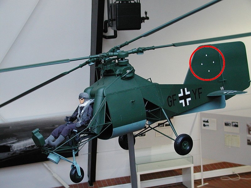 While surfing the net, I discovered someone who had an auction item, actually a WWII German aircraft relic, that is supposed to be part of Flettner 282 helicopter. He claimed that part (with balkenkreuz insignia on) was cut out by WWII veteran US Army PFC Donald R. Nankervis who sent it to his home back in States as a War trophy. According to the instructions written on the back of the canvas, the item was a part was taken from a German airplane stationed at Hittlers private airport at Ainring village between Teisendorf and Salzburg, Austria. Nowdays http://www.wehrgeschichte-salzburg.at/ExkLuftfahrt.html - Ainring airport museum officials, confirm that the Flettner 282 helicopters were actually stationed there at that particular time period (7th May 1945) and used by the 3rd Reich authorities to serve Berchtesgaden & Berghof residence - this makes the story plausible enough and quite convincing, as far as the Historical data and dates. On the other hand, I have some doubts because at that time, all Kolibri helicopters were supposed to be painted with the Luftwaffe's RLM Green / Light Blue colours and not the Kriegsmarine's Grey. Im also puzzled as to why the US serviceman didnt cut out the entire stammkennzeichen marking, but I think that US soldiers were more interested for balkenkreuz & swastikas insignia trophies at this moment, because they symbolic represented the victory on the 3rd Reich. Possibly, the US troops didnt have in their mind that these items will become very valuable for collectors & scale modelers 70+ years later. Additionally, if the above mentioned sellers story is true, it turns out that the British troops were not the only ones who vandalized some one-of-a-kind (at that time) aircrafts, just to show to their friends & family back home that they fought Germans. Anyway, if the auction item is actually a genuine part of a Kolibri helicopter, the following pics are certainly valuable info, considering the rarity of helicopters color photographs. 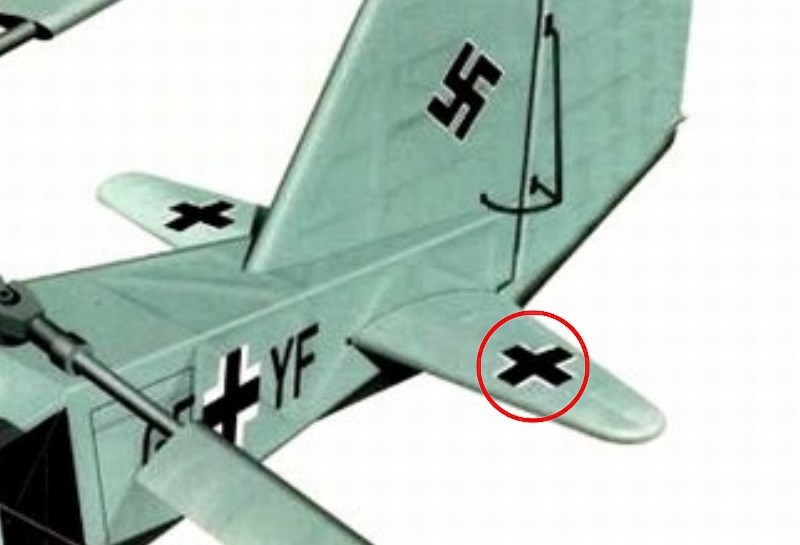
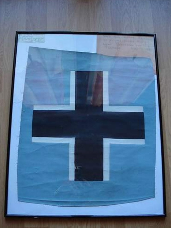
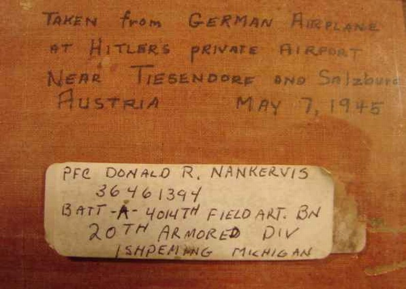
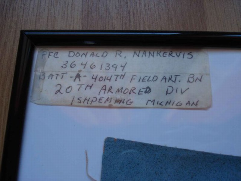 The first couple of 3D printed 1/18 scale Fl-282 helicopter models built by me as commision work on behalf of collectors, had the Kriegsmarines stammkennzeichen (four-letter factory radio code on the fuselage sides and repeated on the both elevator wings undersides), the balkenkreuz & swastikas insignia airbrushed on fuselage - a process that requires precision and careful masking. 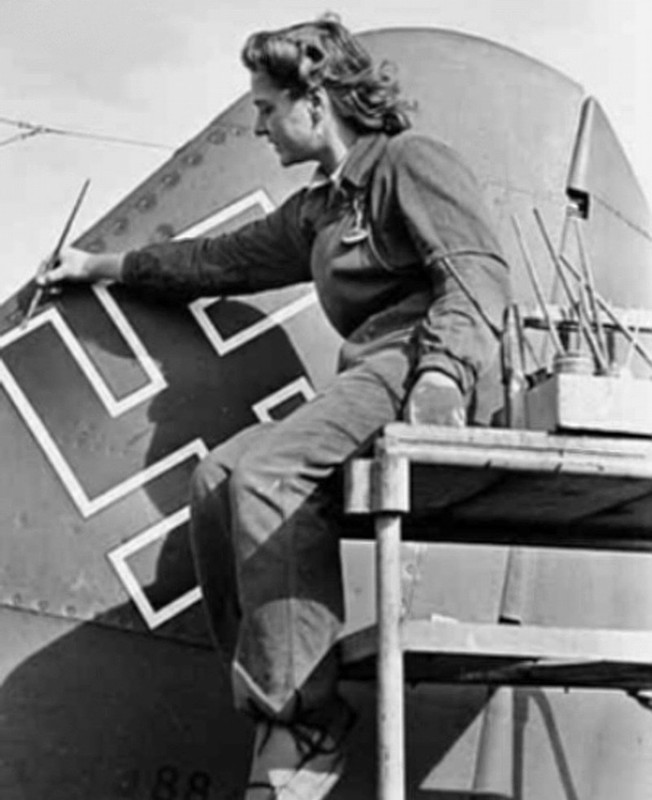 The airbrushed insignia might look nice on big scales when all the repeated masking & airbrushing layers are perfectly executed, but I am a lazy guy and I follow that the easier, the better motto. To do so, I designed the images on Corel, rescaled them on right dimensions and asked Mr. Triantafyllos Metsovitis, owner of https://www.facebook.com/LMDecals - LM Decals to print some right-in-scale Luftwaffe water slide decals for me. Yes, simplicity makes things flow without effort. Luftwaffe insignia print under exact dimensions for a 1/18 scale build, is included into the 102-page ultra-detailed http://www.pdf-archive.com/2015/11/14/1-18-scale-flettner-fl-282-v21-kolibri-instructions/1-18-scale-flettner-fl-282-v21-kolibri-instructions.pdf - 1/18 Fl-282 V21 kit building instructions manual which can be found http://www.pdf-archive.com/2015/11/14/1-18-scale-flettner-fl-282-v21-kolibri-instructions/1-18-scale-flettner-fl-282-v21-kolibri-instructions.pdf - HERE as a PDF format downloadable file. 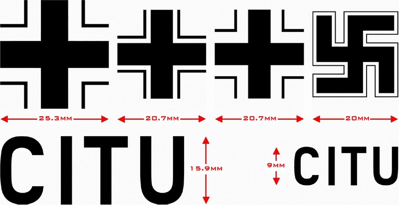
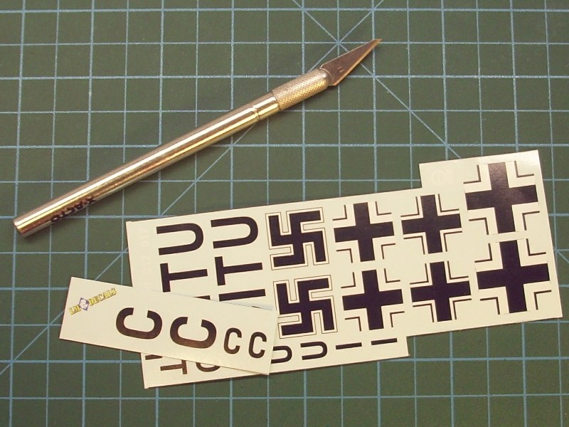 I used a soft brush to apply a light coat of Microscale MicroSol to soften the water slide decal and allow it to become part of the surface. As soon as the water slide decals were dry, an acrylic gloss coat applied to seal the result so far. Once the acrylic gloss coat has cured, I tried to wash the paint by brushing Winter Streaking Grime available by AK Interactive as AK014 filter, until the desired colour density is achieved. The outcome had tonality differences and looked like been highlighted by the sun while shades softly blend each other. Some of the wash mixture is re-applied and the wash being wiped completely out of the narrow points. 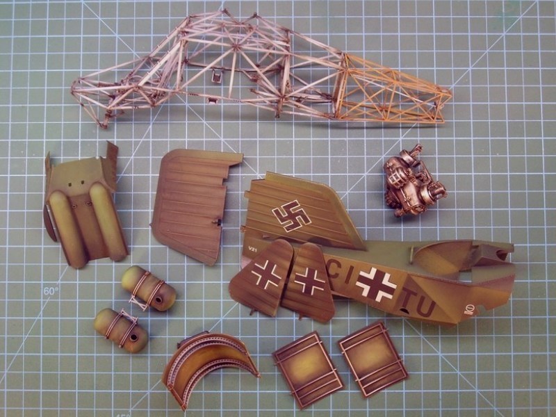 |
Mesajı Yazan: Jolly Roger
Mesaj Tarihi: 10/02/2016 Saat 22:47
|
I think my eyes hurt and my mouth is fairly dry at the same time drooling(not to the blond don't worry). Your work seriously makes me want to quit this hobby....ehehe hehehe.... ------------- Consume Ergo Sum |
Mesajı Yazan: Nick_Karatzides
Mesaj Tarihi: 17/02/2016 Saat 03:25
|
Setting as a task to build the model in such a way that all the maintenance hatches, removable doors, hoods & sliding panels would remain opened to make helicopters internal structure visible, building and later painting & weathering as required a 7-cylinder radial engine is something I should also take care of. Actually, the models observer can easily have a closer look inside the helicopters belly and also check detail on the - visible by any angle - engine details same time. Since the engine would be installed inside the helicopter's belly in the fuselage center-section, a second engine also 3D printed to be placed onto a wheeled stand and present it nearby helicopter, as it would be there for maintenance purposes - just a diorama scene idea. These two engines are almost identical with only difference that the first one is designed to fit into the helicopters transmission unit, while the second is equiped with a bezzel to fit a propeller and is designed to be displayed on the wheeled stand. For those who might be interested, both 7-cylinder radial engines are available http://www.shapeways.com/shops/anyuta3D?section=Engine+models - HERE as 3D printed models under 1/16 and 1/18 scale, with or without the wheeled stand. 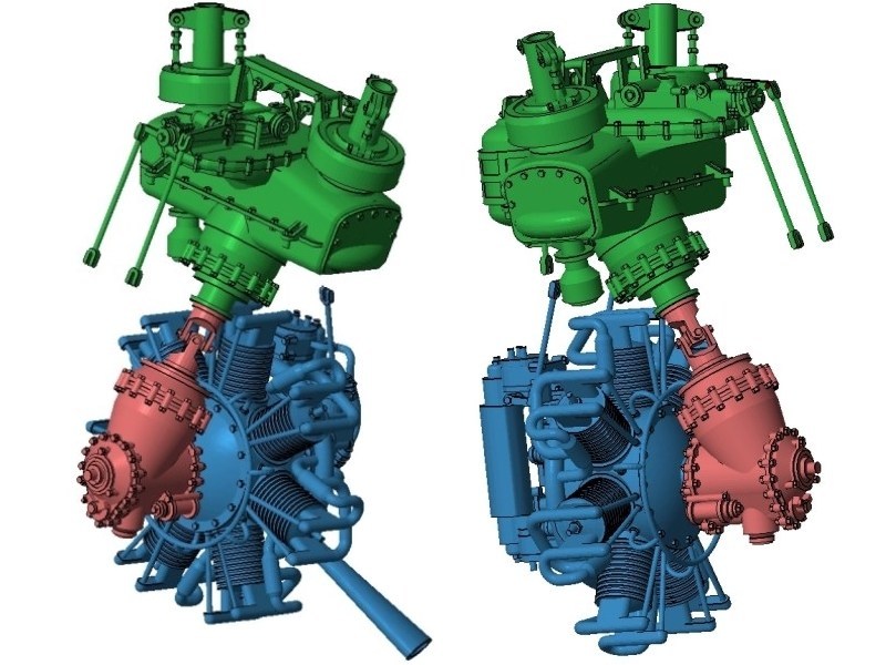
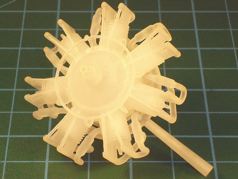
 As soon as both engine miniatures unpacked from plastic bags shipped from Shapeways and carefully examined, they were dipped into White Spirit for a couple of minutes to clean the oil & wax traces left from MJM process while 3D printing. Shortly after parts were washed and allowed to dry, a layer of Ammo Mig Jimenez AMIG2004 White waterborne polymer primer airbrushed over to spot cracks & imperfections and prepare for paintjob. Since I do not consider myself a highclass modeller and I had no experience to paint realistic way radial engines, I thought as a good idea to follow proven techniques described by Mr. Javier López de Anca García into the http://www.migjimenez.com/en/books/263-airplanes-in-scale-the-gratest-guide-english-version.html - Airplanes in scale - The greatest guide book, hoping that I could achieve some decent results. 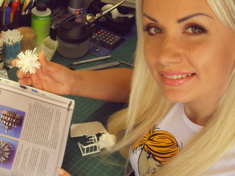 Both engines received an overall base coat of Alclad II metal laquers. When metal paint completely dried, a dark oil paint wash followed using the 502 Abteilung Black by MIG Productions. Later, the aluminum paint got some slightly different burnt tone, by airbrushing thinned MIG-098 Light Blue acrylic crystal around the base of each cylinder and some MIG-093 Red acrylic crystal around the head of each cylinder. The engines crown got some Life Color UA504 RLM 02 Grau acrylic paint and rivets shadowed with Dark Grey oil paint. As for the collector exhaust ring & pipes, they initially were painted with FS3004 Matt Burnt Umber available by Life Color as LC37 acrylic and later repeatedly washed with dense oil paint mixture of Vandyke Brown available by Winsor & Newton, thinned with White Spirit to a consistency between a filter and a wash. Some Light Rust available by AK Interactive as AK046 filter also randomly brushed on exhaust pipes. 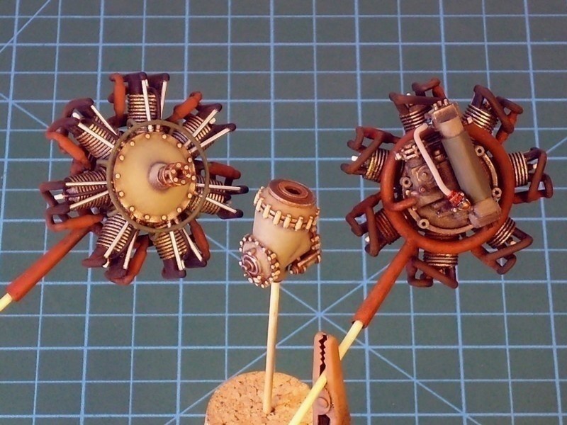 |
Mesajı Yazan: Nick_Karatzides
Mesaj Tarihi: 21/02/2016 Saat 15:29
When powerplant paintjob looked OK to me, it was about time to attempt mounting both 7-cylinder radial engines as required - the first one onto helicopters tubular frame and the second one placed on the wheeled stand. As described into through pages #8 to #14 of the ultra-detailed http://www.pdf-archive.com/2015/11/14/1-18-scale-flettner-fl-282-v21-kolibri-instructions/1-18-scale-flettner-fl-282-v21-kolibri-instructions.pdf - 1/18 Fl-282 V21 kit building instructions manual (which can be found http://www.pdf-archive.com/2015/11/14/1-18-scale-flettner-fl-282-v21-kolibri-instructions/1-18-scale-flettner-fl-282-v21-kolibri-instructions.pdf - HERE as a downloadable PDF format file), the radial engine carefully inserted underneath the main tubular frame and placed in such way to align the engines four slots right onto the frames support beams. Since the nearby battery brackets were too fragile (only 0.4 mm thick), I had to avoid violent moves while installing engine to prevent plastic fracture. As soon as the four slots were simultaneously aligned onto the support beam heads, the engine slided backwards and secured in place by adding a drop of cyanoacrylate super glue.
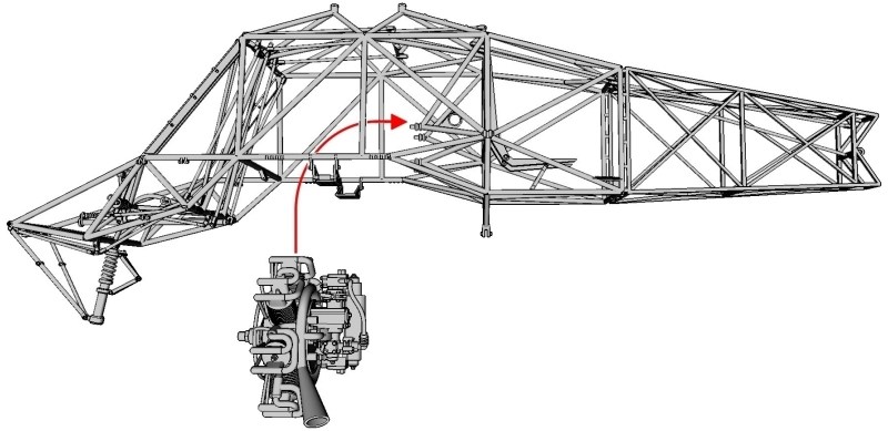
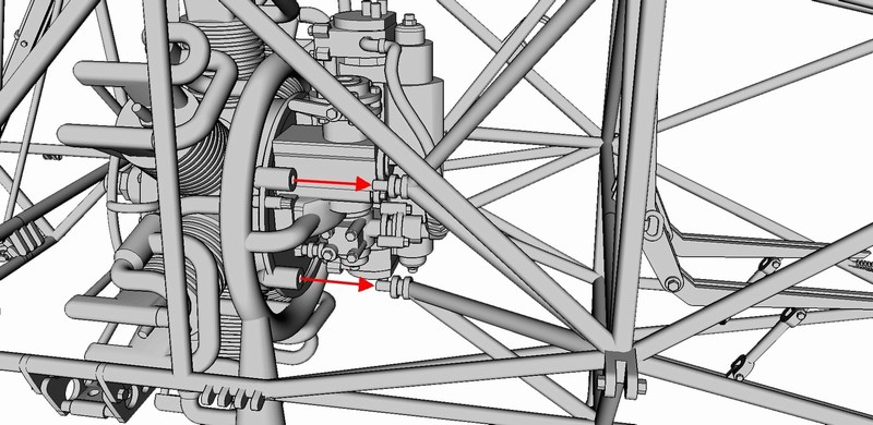 The drive shaft inserted into the transmission units upper opening as shown on the following pictures. The drive shaft designed as a mirrored part and therefore it can be installed either on one side or the other - no matter which side is the top and which is bottom. The transmission unit should be placed on the front of the engine block from which the drive shaft ran to upper gearbox. To do so, the block carefully inserted underneath the main tubular frame, placed in such way to align transmissions rear opening against the 7-cylinder radial engines front end and secured in place by adding a drop of cyanoacrylate superglue. 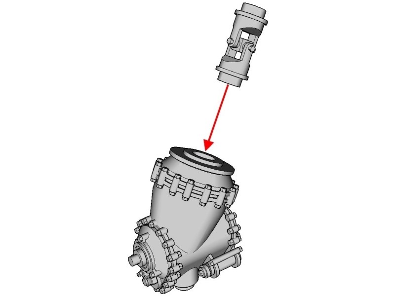
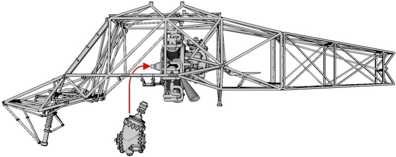
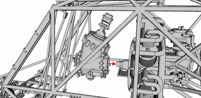 |
Mesajı Yazan: Nick_Karatzides
Mesaj Tarihi: 21/02/2016 Saat 15:34
Well, it took approx 230 pictures and several thousand text words so far, to present the first actual plastic-to-plastic CA gluing. As previously mentioned into CHAPTER III, I prefer to follow the paint individual parts first and assemble model later rule, since I find it more appropriate and surely make my life easier. Seems like the WIP turns from CAD to traditional modeling now, isnt it?
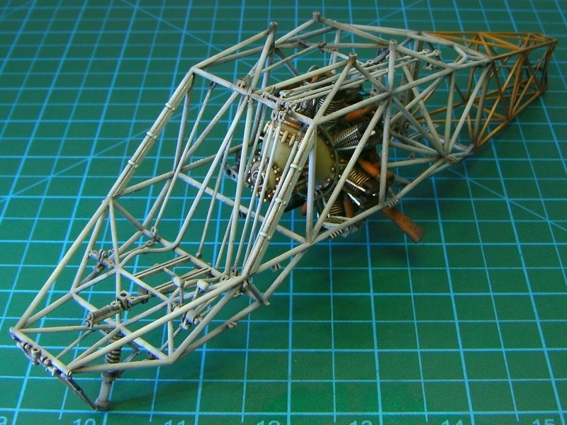
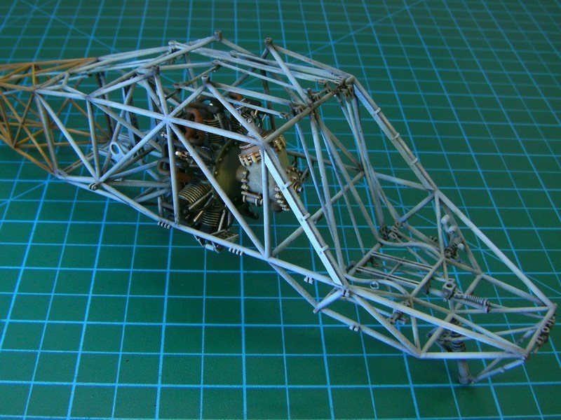
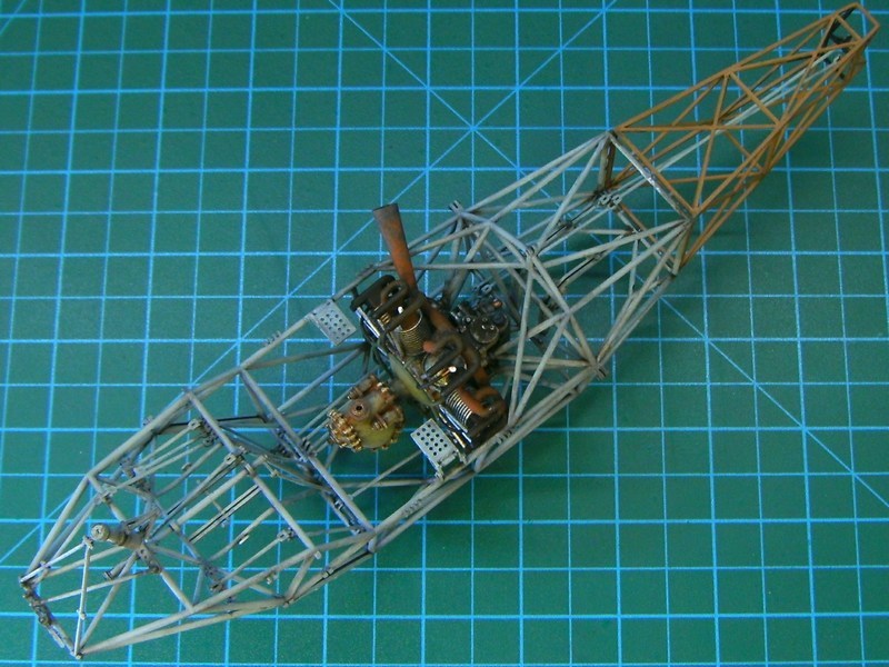 The wheeled stand for 2nd engine, also got painted with some random yellow acrylic paint and later weathered to look paint scraped, with faint areas of rust and a lot of dirt & oil stains. 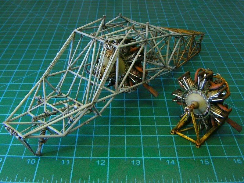
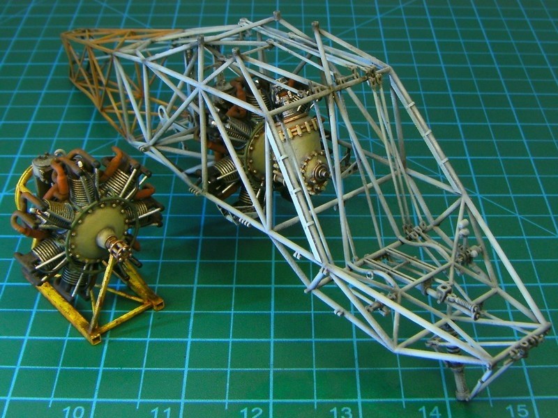 |
Mesajı Yazan: Nick_Karatzides
Mesaj Tarihi: 04/03/2016 Saat 05:35
The engines cooling fan, proved to be the most controversial part of the kit. What really happened? Well, first things first: The Kolibri helicopter was equipped with an air-cooled 7-cylinders radial engine located inside the fuselage center-section and enclosed by outer skin. The powerplant should be efficiently cooled somehow to ensure proper & continuous operation. To do so, air was drawn in through openings beneath the fuselage by a wooden cooling fan with direct drive from powerplant provided strong air flow towards engines cylinders.
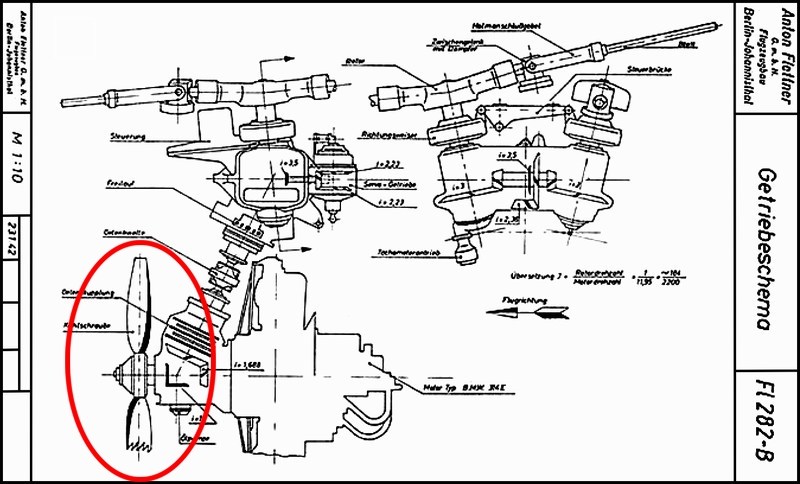 Despite the fact that http://www.schifferbooks.com/the-luftwaffe-profile-series-number-6-flettner-fl-282-2510.html - Luftwaffe Profile Series #6 Flettner Fl 282 ISBN 0-88740-921-0 book (released on 1996 by http://www.schifferbooks.com - Schiffer Publishing , written by Theodor Muhr and originally publilshed on 1991 by Flugzeug Publikations GmbH under the title Flugzeug Profile Flettner Fl 282 Kolibri Varianten) says that continuous cooling provided by an eight-blade wooden cooling fan with direct drive from the engine (page #8), I could not find any front head view photograph of the so-called 8-bladed cooling fan. 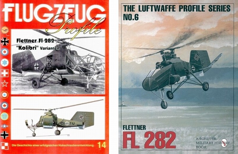
 On the other hand, Ryszard Witkowski author of the http://www.mmpbooks.biz/ksiazki/56 - Rotorcraft of 3rd Reich #5109 ISBN 978-83-89450-43-2 book (released on 2006 by http://www.mmpbooks.biz - MMP - Mushroom Model Publications ), says that the engine was cooled by a wooden twelve-blade fan (page #24), which further complicates the question on the cooling fan issue. So, what type of cooling fan was actually fitted in front of the air-cooled 7-cylinders radial engine? Was it a 8-bladed wooden propeller or a 12-bladed? Or maybe none of the above? 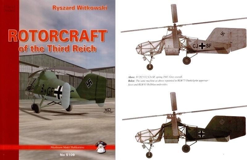
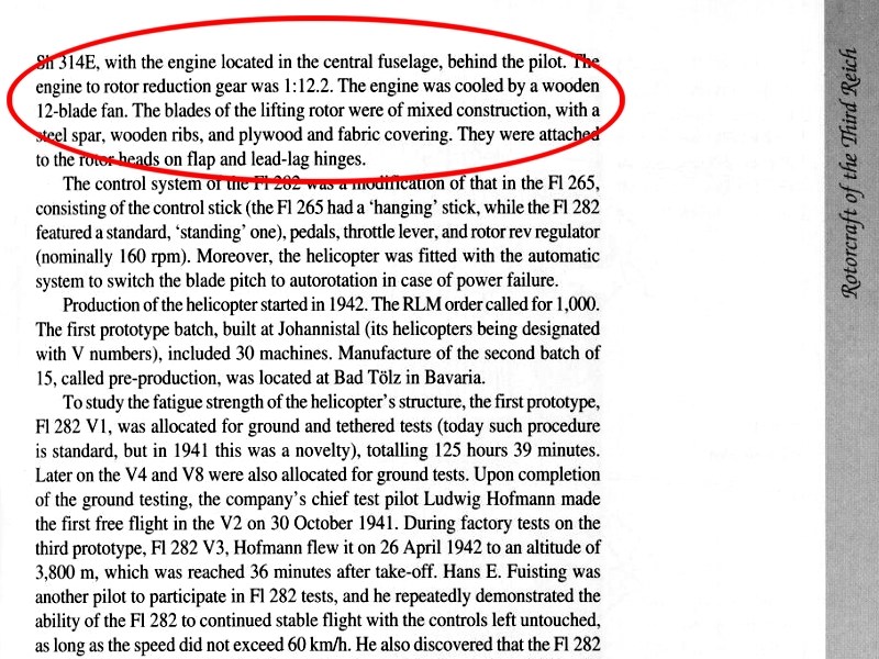 To make things worst, the available diagrams are side-viewed and its not easy to say if the cooling fan is 2-bladed, 10-bladed or 50-bladed. IMHO, when it comes to cooling issue, I think that a multi-bladed fan would be more appropriate. Although a 6-bladed cooling fan had already been used on https://en.wikipedia.org/wiki/Flettner_Fl_265 - Flettner Fl-265 helicopter, the Deutsches Museum officials deny the 8-bladed or 12-bladed fan claim and they strongly support the 2-bladed propeller 90 cm Ø version - after all, they supposed to know better about Flettner 282, dont they? 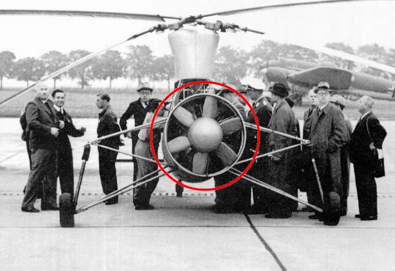 Furthermore, I spotted more errors and incorrect assumptions into the pages of the aforementioned books, which further strengthens my doubts about the accuracy of the given information. For example, it is written that Flettner 282 had not functional elevators and they were just dummy horizontal stabilizers bolted to fuselage frame, which is a huge mistake because blueprints, actual pictures & videos show the exact opposite. Also, it is written that all Kolibris from V20 to V24 versions were completed as two-seaters, which is also a false claim, according to Luftwaffes WWII and Anton Flettner Flugzeugbau GmbH files. Anyway, since I had not a clear evidence of an 8-bladed or a 12-bladed wooden propeller use on Kolibri helicopter and having in mind that both above mentioned books had already few mistakes written into pages, the multi-bladed wooden propeller story seems a little questionable and the 2-bladed cooling fan version is considered as the most plausible, just like appeared on the https://en.wikipedia.org/wiki/Focke-Wulf_Fw_61 - Focke Wulf FW-61 helicopter which already had a single 2-bladed propeller for engine air cooling. I hope my estimations / guesswork are correct and I will not have to publicly perform seppuku because of shame. 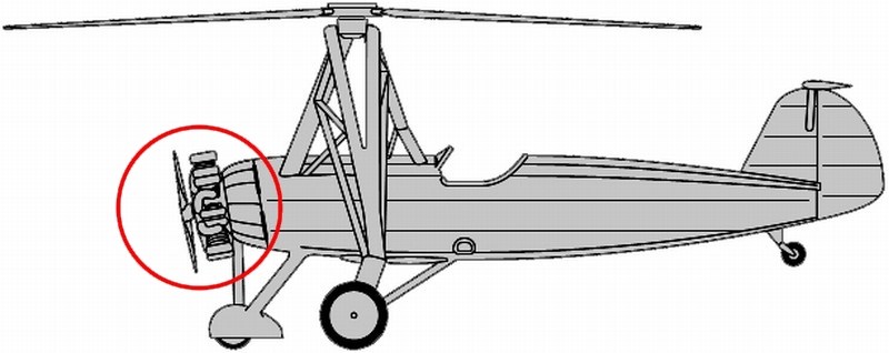
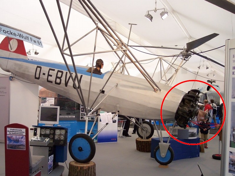 |
Mesajı Yazan: Nick_Karatzides
Mesaj Tarihi: 04/03/2016 Saat 05:45
Once the radial engine mounting process completed, I would attempt to turn a pigs ear to silk purse - in other words, to paint the 3D printed cooling fan in such way to look like made of wood. Since (as commented into previous paragraphs) I had not enough reference of the actual Kolibris cooling fan, I did what most modelers always do - improvise, hoping that final result would look nice! To do so, I used the Life Color UA716 Wood Warm light shade 2 acrylic paint, to overall spray the 2-bladed propeller. Once the acrylic base coat has cured, I used artists oil paints - actually a mixture of Burnt Sienna, Yellow Ochre and Raw Umber in a ratio of 25% to 25% to 50% - to simulate the wood grain and spread a thick layer of paint around. At this point the oils will be workable for several hours. Then, while using a clean & completely dry broad, hard brush, I dragged it over the oil paint, leaving wood grain streaks. As the brush picked up the paint, I wiped it off on a clean, lint free cloth. I left it alone to dry for 24 hours.
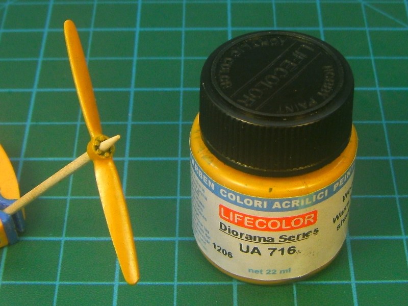
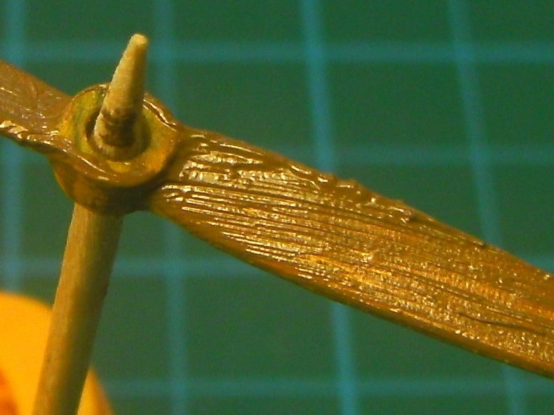
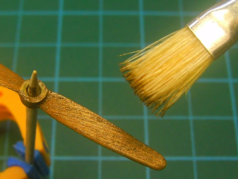 A day later, while oil paint was not fully dry, I used a clean soft brush to blend the streaks, just a little more. As soon as it looked OK to me, I left it few days more to dry completely and then spray it with Tamiya Color X-24 Clear Yellow acrylic, because it also helps bring the grain color out more. 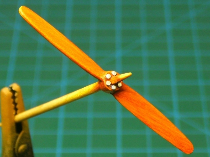 The 2-bladed wooden propeller placed on the front end of the (previously installed) transmission block. So, this is how the assembled block of 7-cylinder radial engine, transmission unit, drive shaft & cooling fan should look like when correctly fit into each other. 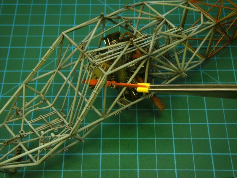
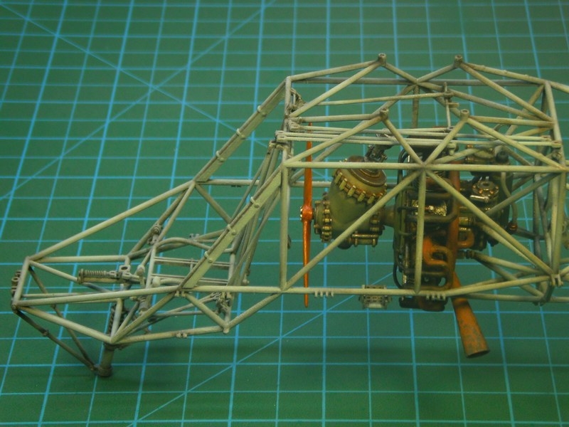
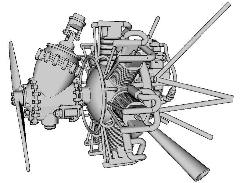 |
Mesajı Yazan: Nick_Karatzides
Mesaj Tarihi: 07/03/2016 Saat 05:38
If the assembly sequence would follow the instructions by-the-book, the two battery packs should be placed on appropriate brackets located on either side of the transmission unit as shown in the picture from the kit manual. Since the original building idea requires to setup the 1/18 scale Kolibri model in such way to look like under maintenance (or refueling) procedure with all the hatches & sliding panels opened or removed, I decided to deviate just a little from the schedule and do something different: To unplug the batteries and place them somewhere else - possibly on some wooden box or the previously mentioned wooden ladder, one of these unrelated to the helicopter structure additional parts which were designed & 3D printed to be used as part of a diorama scene.
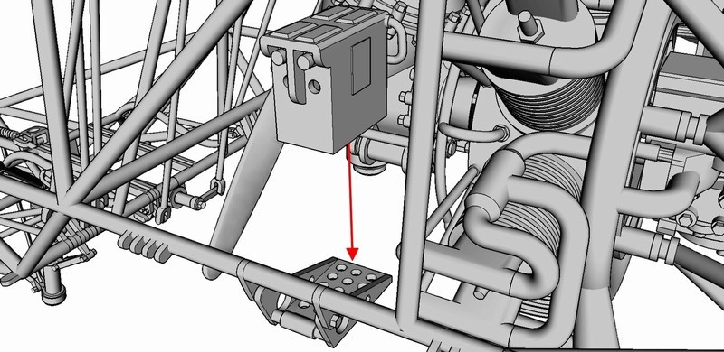 |
Mesajı Yazan: Nick_Karatzides
Mesaj Tarihi: 07/03/2016 Saat 05:48
|
Each one of the 1/18 scale Flettner 282 V21 kits contains two crew seats for the pilot and for the rearwards facing observer. The observers seat consists of two perforated plywood boards, one for the bottom part fixed on a retractable bracket and one for the backrest fixed on frame rails. Cushions are placed over bottom part & backrest plywood boards to provide comfort. On the other hand, the pilots seat consists of a (similar cushion covered perforated plywood board) bottom part only, since he rests his back-pack type parachute against the front fuselage cover. 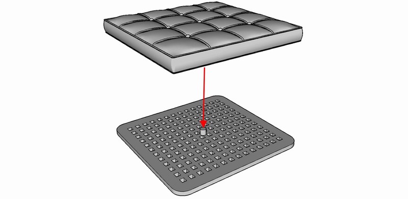
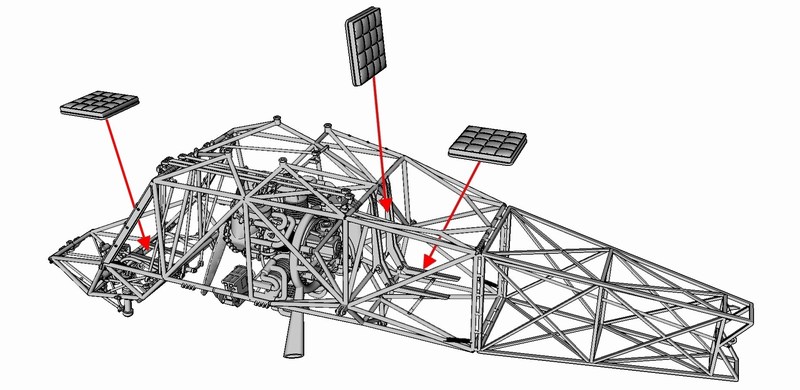 Having just painted the perforated plywood boards and being quite pleased with the outcome, I decided (once again) to deviate from the instructions and skip the cushions installation - after all, the reddish varnished look on plywood boards seems to make a fine contrast with the overall RLM 71 Dunkelgrün FS 34079 and breaks the green monotony. 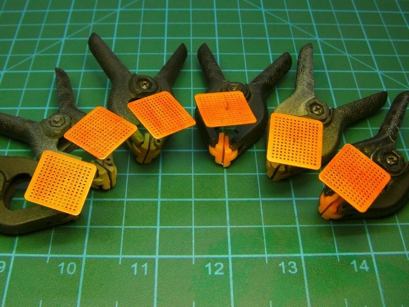
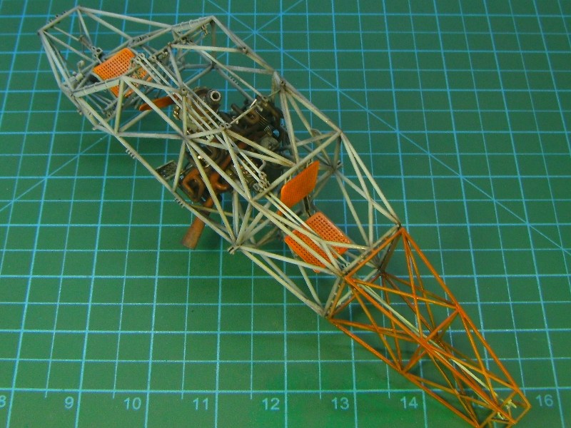 |
Mesajı Yazan: Nick_Karatzides
Mesaj Tarihi: 07/03/2016 Saat 05:56
Those who have followed this thread from the start, will remember that the front fuselage cover had already been covered with an overall dark undercoat and later gradually airbrushed with RLM 71 Dunkelgrün FS 34079 to achieve proper gradations of light. The front fuselage cover patiently awaited the tubular frame painting completion, in order to come the turn to be properly installed. The part carefully dragged in place along the frame tubes, until reached down on the pilots seat & secured in place with a drop of cyanoacrylate super glue.
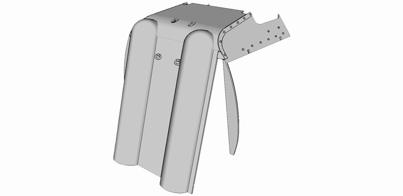
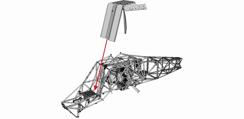
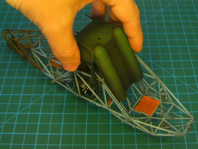
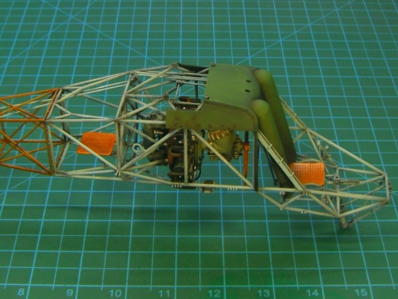 |
Mesajı Yazan: Nick_Karatzides
Mesaj Tarihi: 09/04/2016 Saat 10:01
The first two production model kits under 1/18 scale, were 3D designed such way to have the seatbelts & buckles embossed on the crew seat cushions - a tactic that later altered, since customers mostly prefered to add their own harness or leave the miniature helicopter free of straps webbing. For this reason, the seatbelts shown into following pictures were built from 2.5mm to 3.5mm wide masking tape and photoetched set by Eduard, under 1/20 scale. The seatbelts later got some brownish & khaki paint - so as to make sharp & nice looking contrast against the reddish varnished plywood seatboards and the overall RLM 71 Dunkelgrün FS 34079 painted airframe cover.
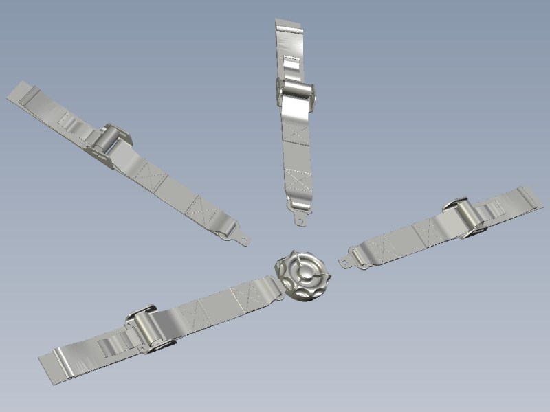
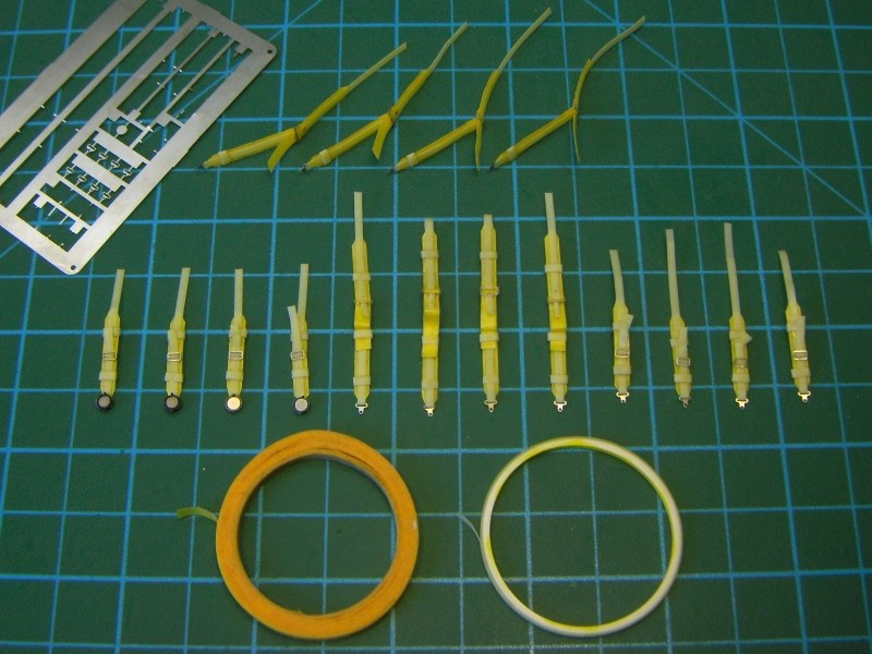 |
Mesajı Yazan: Nick_Karatzides
Mesaj Tarihi: 09/04/2016 Saat 10:12
|
The rear fuselage section on real Flettner 282 helicopter was made of doped fabric covering over the steel and wooden frame. Those who have followed this thread from the start, will remember that the rear fuselage section had already been covered with an overall black / dark brown undercoat and then gradually lighten the surfaces to replicate the way that sunlight hits on large objects, following the Francois Verlindens old-fashioned way (which was re-introduced and become popular around the scale modelling community, by its new modulation name). The dark undercoat, gradually airbrushed with RLM 71 Dunkelgrün FS 34079 to achieve proper gradations of light, trying to balance between realism factor and artistic expression. IMHO modulation effect does not accurately replicate the reality, but it looks so artistically attractive and becomes easily accepted by our visual subconscious. Custom made water slide decals applied and later everything washed by brushing Winter Streaking Grime AK014 filter available by AK Interactive, until the desired colour density is achieved. As described into pages #25 to #27 of the ultra-detailed http://www.pdf-archive.com/2015/11/14/1-18-scale-flettner-fl-282-v21-kolibri-instructions/1-18-scale-flettner-fl-282-v21-kolibri-instructions.pdf - 1/18 Fl-282 V21 kit building instructions manual (which can be found http://www.pdf-archive.com/2015/11/14/1-18-scale-flettner-fl-282-v21-kolibri-instructions/1-18-scale-flettner-fl-282-v21-kolibri-instructions.pdf - HERE as a downloadable PDF format file), the rear fuselage cover part carefully dragged along the miniature's wooden frame, until reached down on the transmission pivots & secured in place with a drop of cyanoacrylate super glue. 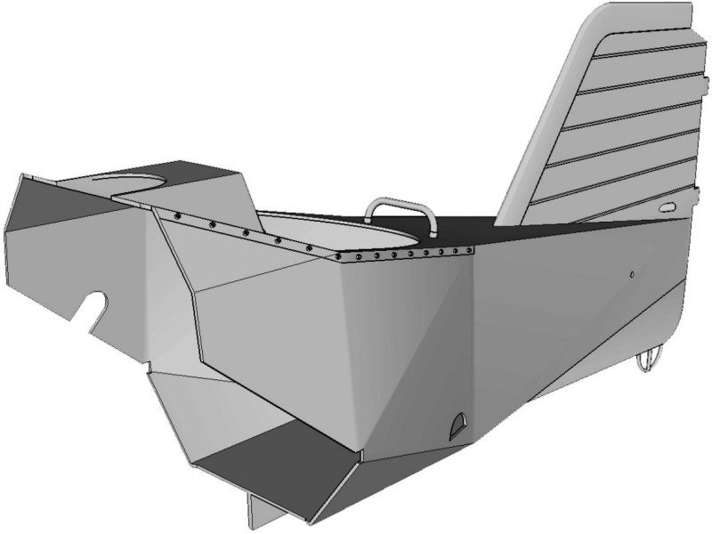
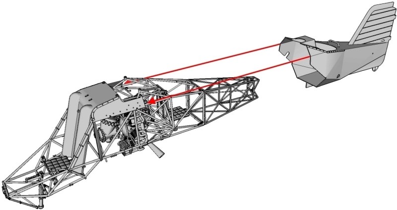
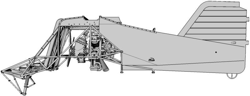
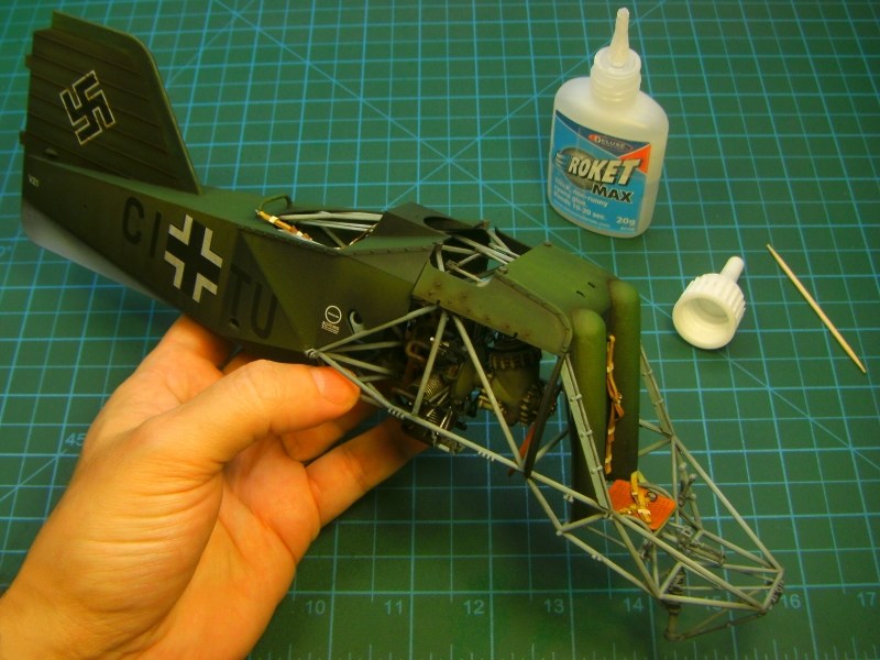 |
Mesajı Yazan: Nick_Karatzides
Mesaj Tarihi: 11/04/2016 Saat 17:22
A year passed since April 11th 2015. A day like today and the whole World seems so empty when you miss your other half.
 |
Mesajı Yazan: Nick_Karatzides
Mesaj Tarihi: 11/04/2016 Saat 17:24
|
Orjinalini yazan: Nick_Karatzides
A year passed since April 11th 2015. A day like today and the whole World seems so empty when you miss your other half. Wishing to remember this day and honor http://zone-five.net/showpost.php?p=309405&postcount=20 - her sweet & loving memory, last week http://www.shapeways.com/shops/anyuta3D - Anyuta 3D decided to make an offer for few fellow modelers & skilled craftsmen by sending a limited number of coupons. During last week, few hand-picked forum members, specialy selected talented & promising modelers, received (or about to receive) their own 3D printed http://shpws.me/L3F4 - 1/18 scale Flettner Fl-282 Kolibri cutaway model kits. By the time these lines are written, the parcels are on their way to modelers postal addresses. 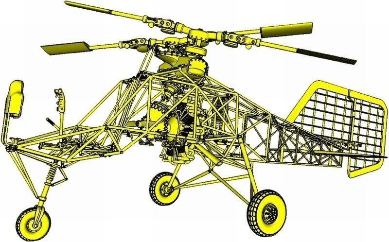
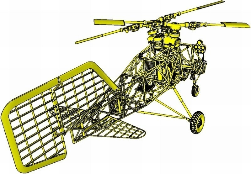 |
Mesajı Yazan: Nick_Karatzides
Mesaj Tarihi: 14/04/2016 Saat 23:13
|
Steering of the Fl-282 was achieved by a combination of the rudder and differential collective pitch change on the two rotors, but only the rudder could give steering during autorotation since collective pitch was then ineffective (another reason for the large rudder area). Rudder fin (of very generous area), was made of wood and covered by fabric, with max 40° deflection left or right. This large area was necessary because much of it was ineffective due to the poor aerodynamic shape of the fuselage causing rearwards flow separation and turbulence. The vertical stabilizer and the elevators were also made of wood, with plywood leading edge and fabric covering, bolted to fuselage frame.
As described into pages #29 to #32 of the ultra-detailed http://www.pdf-archive.com/2015/11/14/1-18-scale-flettner-fl-282-v21-kolibri-instructions/1-18-scale-flettner-fl-282-v21-kolibri-instructions.pdf - 1/18 Fl-282 V21 kit building instructions manual (which can be found http://www.pdf-archive.com/2015/11/14/1-18-scale-flettner-fl-282-v21-kolibri-instructions/1-18-scale-flettner-fl-282-v21-kolibri-instructions.pdf - HERE as a downloadable PDF format file), the rudder fins slots should be aligned onto horizontal stabilizer's hinges as shown on the following pictures. I tried dry fit testing before the final gluing & part secured in place by adding a drop of cyanoacrylate superglue. Since the rudder fin can be instaled turned (with max 40° deflection left or right), the servo bars should be inserted into slots & placed as required. Notice that if the rudder fin is tilted left or right or neutral, the rudder pedals at cockpit area & nose wheel, should be also positioned accordingly. 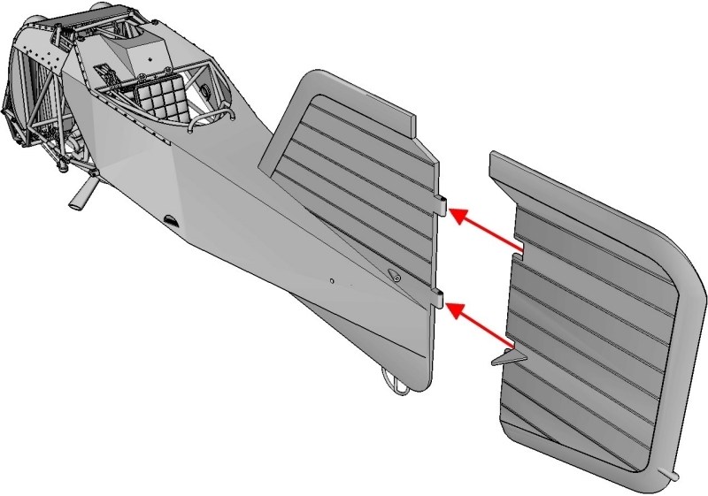
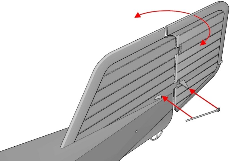
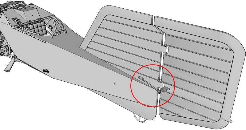 The two horizontial elevator fins should be installed by inserting the 1.4 mm Ø pins through side openings of rear fuselage section as shown on pictures and securing in place with a drop of cyanoacrylate superglue. Keep in mind that if the horizontial elevator fins are placed tilted up or down or neutral, the cyclic / KG.13 control stick at cockpit area, should be also positioned accordingly. 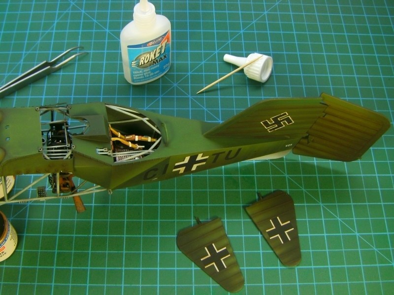
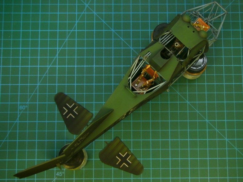
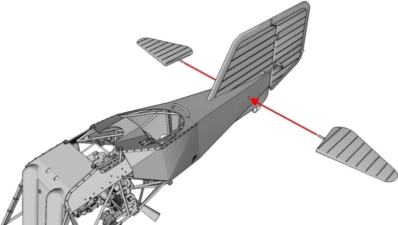
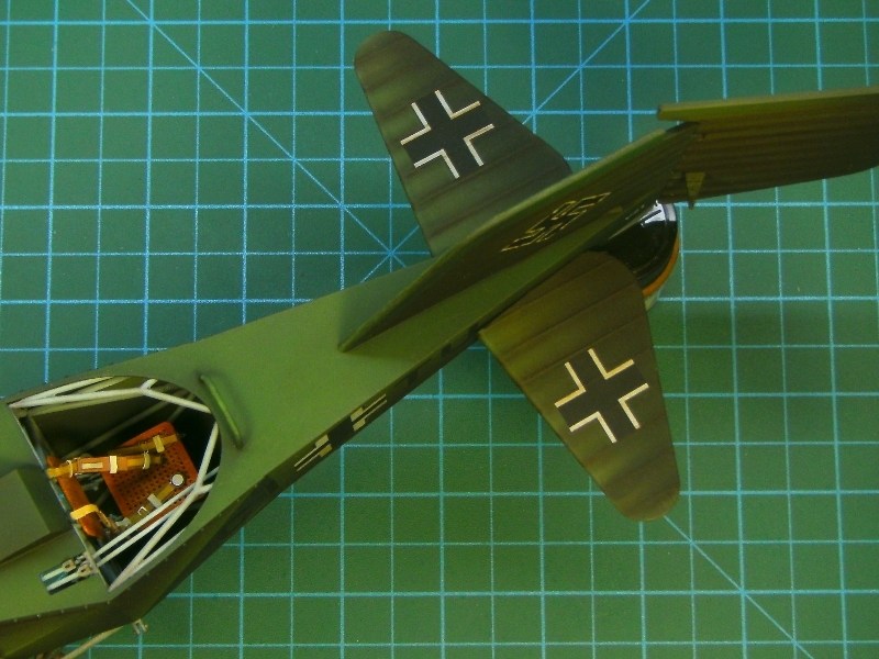 Under normal conditions, each helicopters registration ID was duplicated under elevator fins. After all, there are many photographic evidences certifying this feature, just like the following picture showing the CJ-SK registered Fl-282 V17 helicopter, crashed at Travemünde on April 13rd 1944, while test pilot FliegerStabsingenieur (Luftwaffe Major) Gerhard Geike was attempting a diving nose-down and then pulling back technique landing. 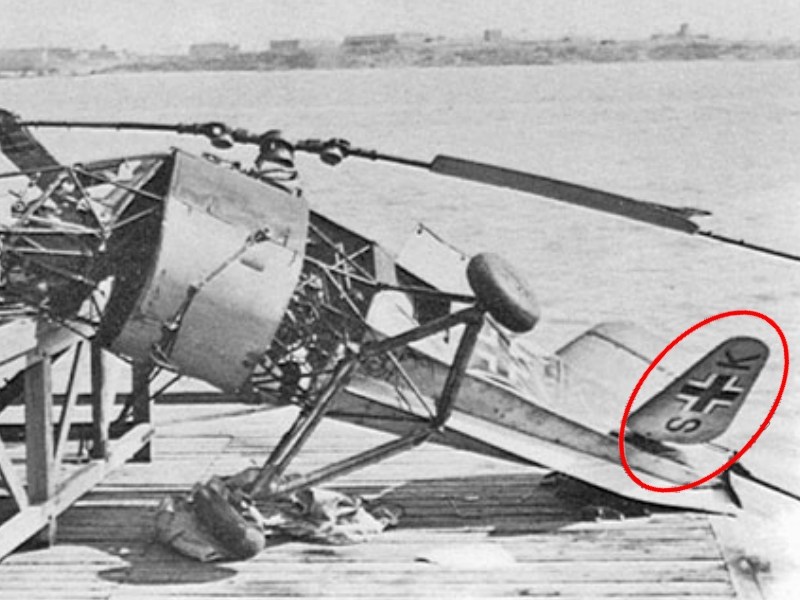 However, there is a rare photograph of the already mentioned CJ-SN registered Fl-282 V20 helicopter assigned to Staffel 1/196 at Pillau AB as found & captured by the British Army, that clearly shows registration missing under the elevator fins. Luckily, the picture taken before helicopter been brutally disassembled, doped fabric ripped away & removed from fuselage, clipped rotor blades cut off & never seen again since that day and remaining framework wreckage with upper rotor transmission parts transferred back to UK as a War trophy and ended up as souvenirs. 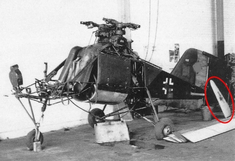 |
Mesajı Yazan: Nick_Karatzides
Mesaj Tarihi: 18/04/2016 Saat 04:29
|
When I started this project almost two years ago, I had in mind to also present the cutaway model kit version step-by-step WIP, as soon as the full fuselage model kit building would have been completed. Actually, both versions already built multiple times as commision work for collectors (for example click https://s25.postimg.cc/j1ptqr5lr/IMAGE_0211.jpg - HERE to see both versions frames placed side-by-side, while painting process) and I only had to write the text and later attach the pictures shot during assembling & painting process. - http://shpws.me/L3F4 - 1/18 scale Flettner Fl-282 V21 Kolibri model kit - CUTAWAY version - http://shpws.me/KdjE - 1/18 scale Flettner Fl-282 V21 Kolibri model kit - FULL FSG version Considering that over 130+ model kits of both versions sold since http://www.anyuta3d.com - Anyuta 3D produced the very first 3D printed V6 version kit under 1/18 scale on early 2014 and due to the fact that the V21 cutaway version became quite popular the last few days, I am now thinking to change a little the basic plan and let the cutaway version step-by-step building edit into the full fuselage version WIP and present them both as a parallel project into a single forum thread.
As you all understand, the cutaway version is actually based on the previously released full fuselage model kit, but more than 50% of parts should be CAD designed from the start in order to achieve best results. Although both versions are accurate miniatures of the Kolibri V21 helicopter under 1/18 scale, each one follows different assembling methodology. During the CAD phase, the individual kit parts designed in such way to be as easy as possible for the average modeler to build the model. To do so, the total number of tiny parts reduced (as possible) and different components combined into one part only. IMHO, building something from scratch is not so difficult - after all, we all tried some scratch once in a while. On the other hand, designing a helicopter model from scratch, exploding it into 60+ parts and make each one of them possible to get re-assembled & combined all together in order to create a miniature, is not a piece-of-cake. Speaking of a cutaway, the design difficulty factor gets multiplied. 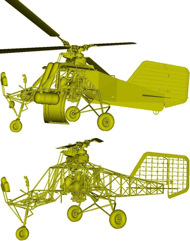 If you download the http://www.pdf-archive.com/2015/11/14/1-18-scale-flettner-fl-282-v21-kolibri-instructions/1-18-scale-flettner-fl-282-v21-kolibri-instructions.pdf - 102-page "full fuselage" and the http://www.pdf-archive.com/2015/11/17/1-18-scale-flettner-fl-282-v21-kolibri-cutaway-instructions/1-18-scale-flettner-fl-282-v21-kolibri-cutaway-instructions.pdf - 67-page "cutaway" PDF formated building instructions manuals, you'll notice the building process differencies on the first pages. Both versions have exact same dimensions when models fully built, but each assembling process differs a little. For example, as shown into following picture: - The "full fuselage" version kit is equiped with four full-length rotor blades (measuring approx 28 cm long each), but the "cutaway" version has the short / chopped rotor blade parts (marked into red ellipse), to simulate the Kolibri found by British Army and now preserved by Midland Air Museum, in cutaway condition. - The "full fuselage" version's main tubular frame is a little shorter (marked into red circle in following picture) than the normal-length cutaway version's tubular frame. This is because the "full fuselage" version's rear fuselage cover part (which simulates the doped fabric covering over the steel & wooden frame and moreover has the vertical stabilizer attached on) should be dragged along the miniature's wooden frame, until reached down on the transmission pivots. So, as you understand, few milimeters of empty space are needed to ensure the appropriate contact. - The "full fuselage" version's main tubular frame is equiped with a "sleeve" (marked into purple ellipse in following picture) over the front tubular frame. Actually this is a bracket made of wood to support avionics & radio either side of the pilot at cockpit area. This "sleeve" part as well as some others like eg batteries, avionics & radio, 25 litres cylindrical fuel tanks mounted externally on both sides of the pilot, seat cushions etc are also missing from the "cutaway" version. - The undercarriage support (marked into blue ellipse in following picture) is different on each version. Although both versions will show the same on this undercarriage support area when models are buit, the full fuselage version's main tubular frame is missing this part, since it is already attached on the rear fuselage cover part. 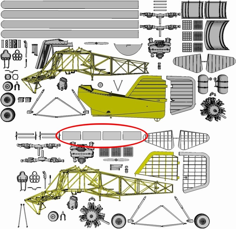
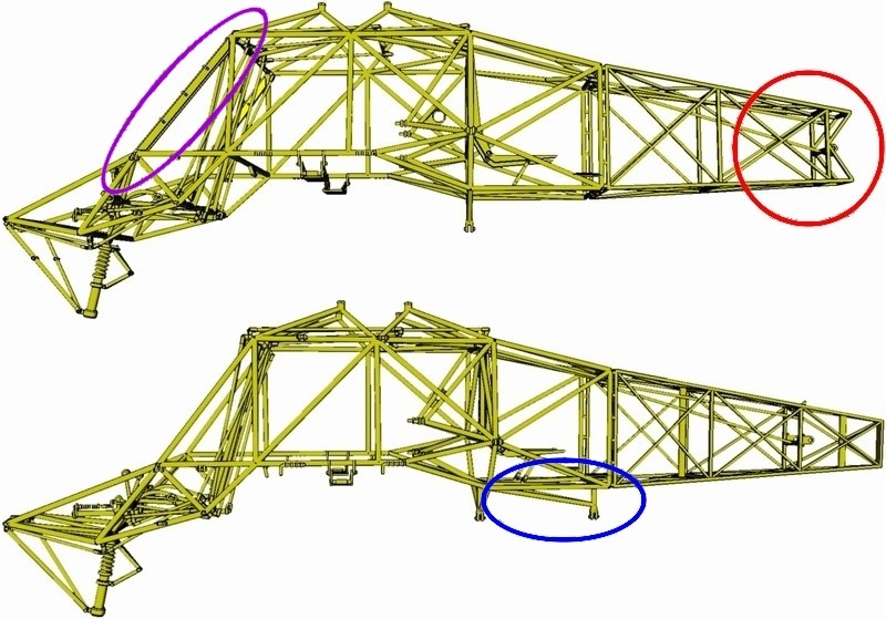 - The vertical stabilizer of the cutaway version kit is offered as a separate part, which should be glued on the wooden frame. On the other hand, on full fuselage version kit, the vertical stabilizer is already attached on rear fuselage cover and offered as combined items. 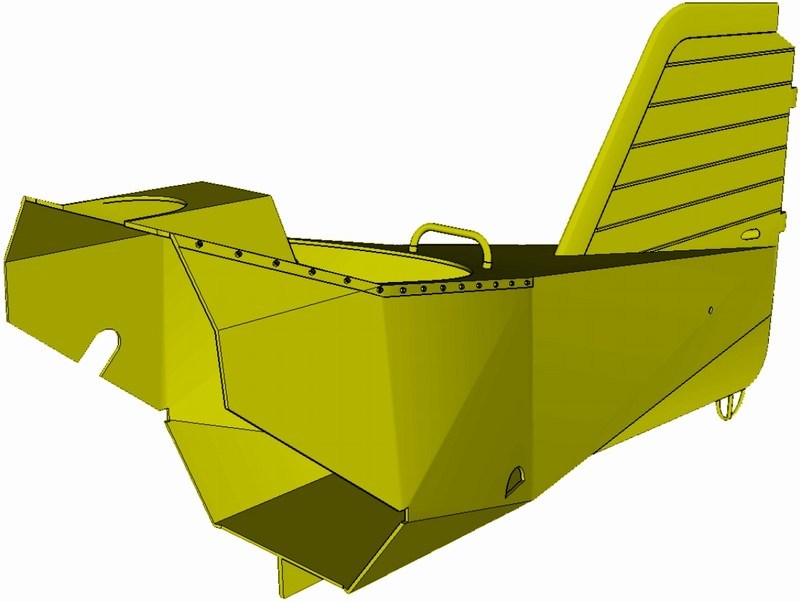
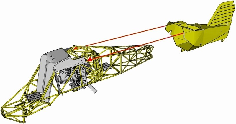
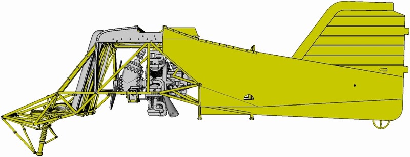
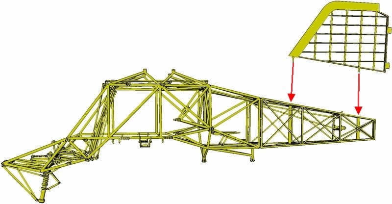 |
Mesajı Yazan: Nick_Karatzides
Mesaj Tarihi: 18/04/2016 Saat 04:44
After studing the available reference (few hundreds of pics, blueprints, slides & negatives, videos, technical data and original Luftwaffe's text documents) kindly offered from a variety of sources such as Deutsches museum flugwerft schleißheim, Hubschraubermuseum Bückeburg, Midland air museum, a fellow modeler from Germany whose grandfather was a worker in the Anton Flettner Flugzeugbau GmbH factory at the time when the helicopters manufactured, Mr. Steve Coates author of the "Helicopters of the Third Reich" book and ofcourse Mr. Google (modeler's best friend), the already existing CAD digital file converted to Kolibri cutaway. Now, the model is ready to be forwarded to the 3D replicator and become an actual physical object under 1/18 scale, within short time.
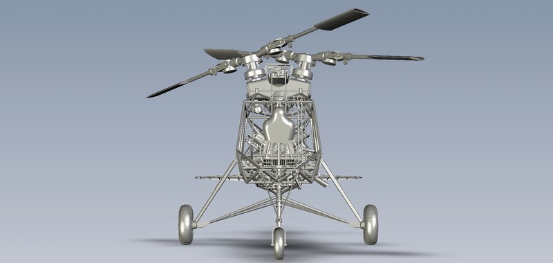
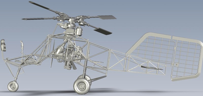
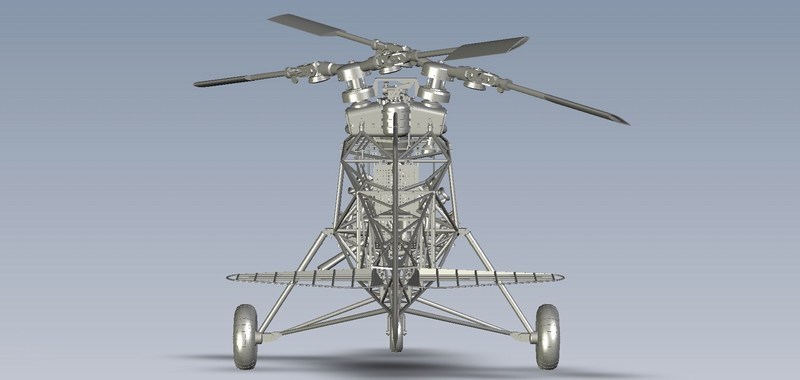
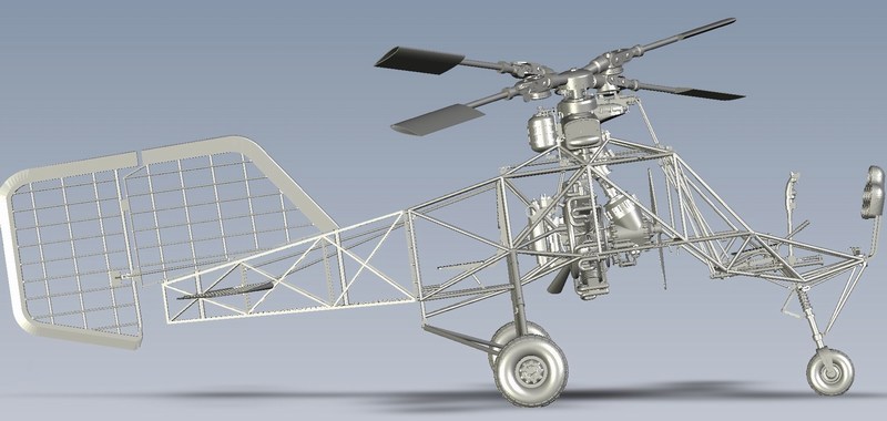
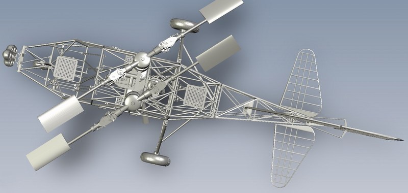 |
Mesajı Yazan: Nick_Karatzides
Mesaj Tarihi: 18/04/2016 Saat 04:49
Approx 50% of the components are copied & pasted from the already existing full fuselage version and (lucky me) I did not had to design everything from the start. For example, the complex of intermeshing rotor gearbox, the 7-cylinders radial engine, the 24° angled rotor heads etc. On the other hand, all the wooden frame parts such as the vertical stabilizer, the rudder fin, the horizontial elevator fins and rear fuselage frame details, were CAD designed from the start. Ofcourse, the cutaway version was also built with all included truss-type welded tubes and drive shaft rods with universal joints attached on frame. IMHO, that was mostly preferred because all basic parts should be accurately pre-installed in place without any glue, putty, sanding etc.
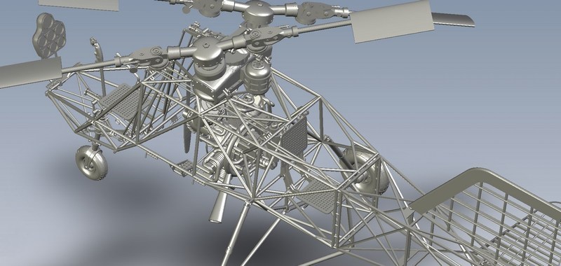
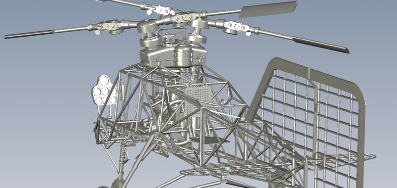
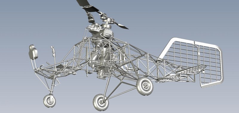
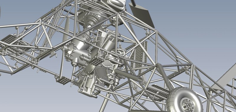
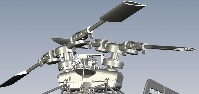
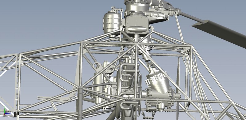 |
Mesajı Yazan: Nick_Karatzides
Mesaj Tarihi: 18/04/2016 Saat 04:57
After digitally building the Fl-282 Kolibri cutaway 3D model using only mouse clicks, I saved it as an STL - STereoLithography format binary file and forward it on the 3D replicator to start generating the individual parts of the actual scale model. Once again, I used best available tools & plastic material and asked from Shapeways digital fabrication lab (equipped with a high-precision & high-cost ProJet HD 3000 machine for creating custom made-to-order products), to 3D print it. The 1/18 scale Fl-282 V21 Kolibri cutaway model kit consists of more than 40 different 3D printed parts made of matte translucent plastic material - in fact, the kit parts are quite more, but smaller in size are interconnected on same sprue frame which is counted as one part. Kit was CAD designed and 3D produced in such way to simplify assembling process while maintaining necessary details required by the scale size. Following the instructions described into the 67-page ultra-detailed http://www.pdf-archive.com/2015/11/17/1-18-scale-flettner-fl-282-v21-kolibri-cutaway-instructions/1-18-scale-flettner-fl-282-v21-kolibri-cutaway-instructions.pdf - 1/18 Fl-282 V21 cutaway kit building instructions manual (which can be found http://www.pdf-archive.com/2015/11/17/1-18-scale-flettner-fl-282-v21-kolibri-cutaway-instructions/1-18-scale-flettner-fl-282-v21-kolibri-cutaway-instructions.pdf - HERE as a PDF format downloadable file), the assembling process becomes easy.
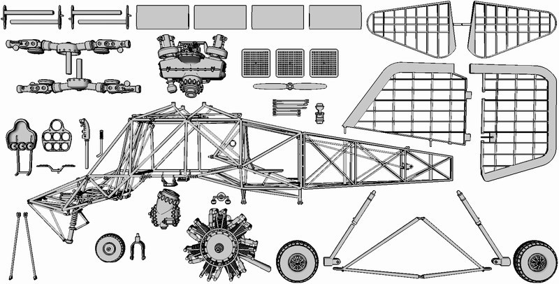
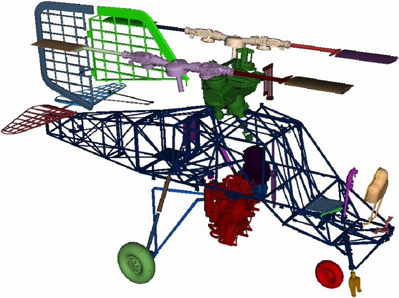
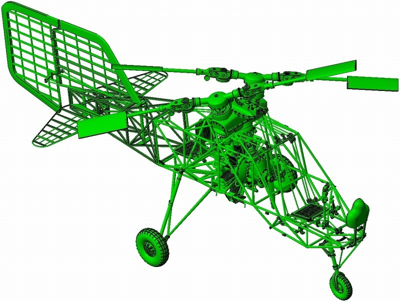
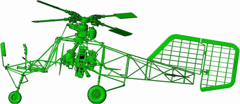 When printing is finished, the model parts are removed from the tray and placed into an oven that melts away the wax support material. Next, the models are placed into an a ultrasonic oil bath to remove any remaining wax residues, and then a ultrasonic water bath to remove any oil on the model. Final inspection and dry by hand follows for every single model part. Although the ProJet HD 3000 prints in high resolution (16 microns per layer) and can easily produce high detailed parts as small as 0.1 mm, it is better to avoid printing such small parts because they could easily get lost while washed into ultrasonic bath later, for wax residues removing. Each complete model kit takes about 5 to 7 days to get produced after order due to increased workload for 3D printed manufacturing demand in Shapeways factory. 

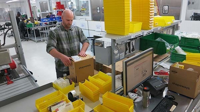 |
Mesajı Yazan: Nick_Karatzides
Mesaj Tarihi: 18/04/2016 Saat 05:02
As soon as 3D printing process completed, the produced parts were cleaned & checked for broken parts or imperfections by Shapeways 3D printing lab specialized personnel. Later, everything carefully packed and shipped to my home address using UPS 24hrs delivery service. Once again, I was happy to hold my own custom 3D printed model kit, CAD designed with my laptop and later converted to an actual physical object, under my preferable 1/18 scale.
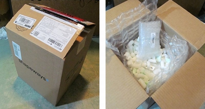
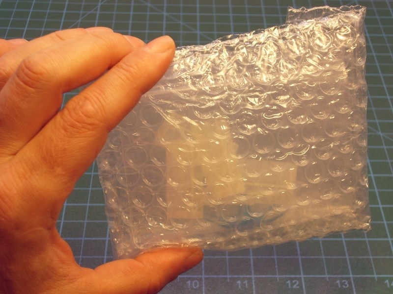
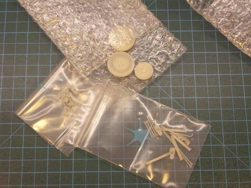
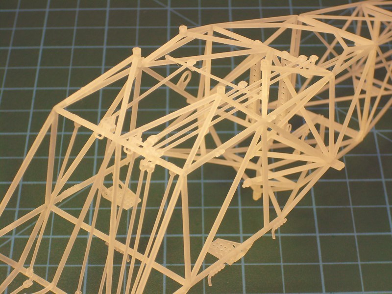
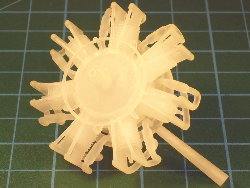
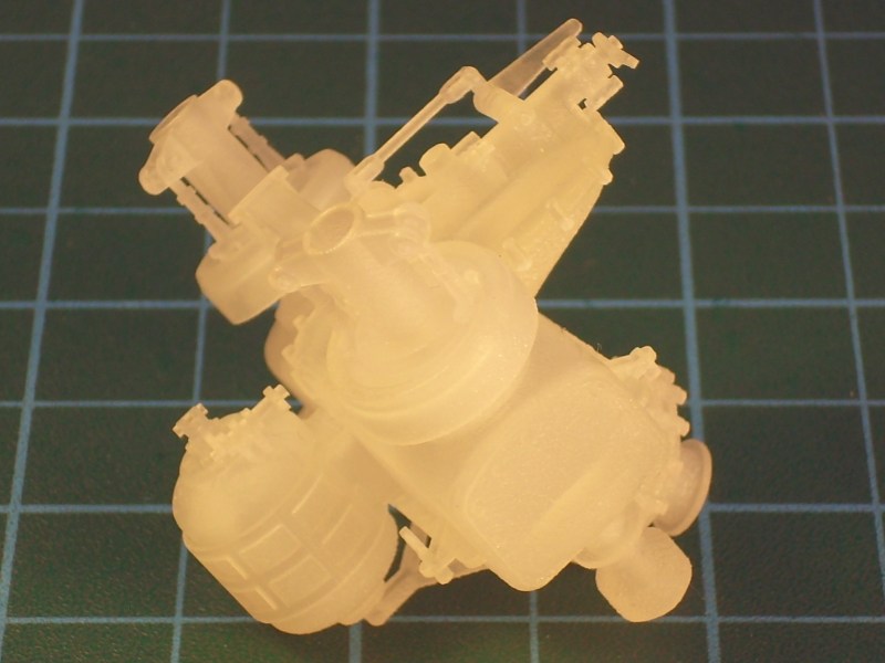
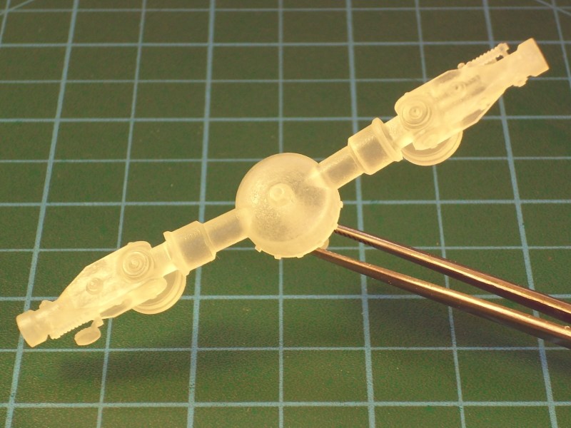
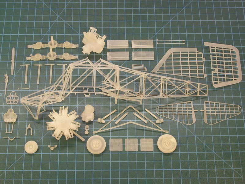 |
Mesajı Yazan: Nick_Karatzides
Mesaj Tarihi: 18/04/2016 Saat 05:08
Some additional parts unrelated to the helicopter structure, also 3D printed to be used later as part of a diorama scene. For example few http://shpws.me/KeaD - 1/18 scale 20 litres fuel canisters , a couple of http://shpws.me/KeeV - 1/18 scale 200 litres fuel drums as used by Wehrmacht, Luftwaffe & Kriegsmarine during WWII with Kraftstoff 200L Feuergefährlich Luftwaffe and Kraftstoff 20 L Feuergefährlich 1941 inscriptions engraved or embossed on side, a http://shpws.me/KX31 - 1/18 scale fuel hand pump and one http://shpws.me/Kg3S - 1/18 scale wooden 3-steps ladder as used by Luftwaffe WWII ground crews and technician personnel for ground vehicle & aircraft maintenance procedures.
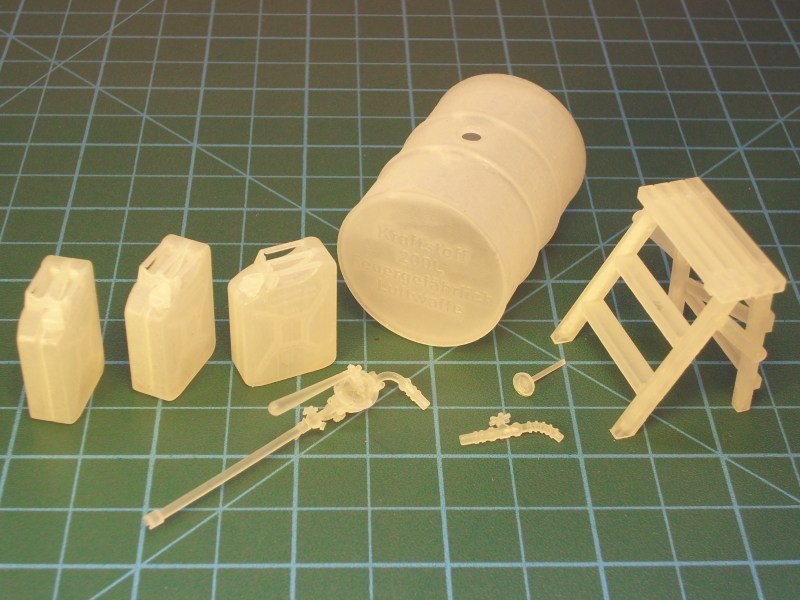
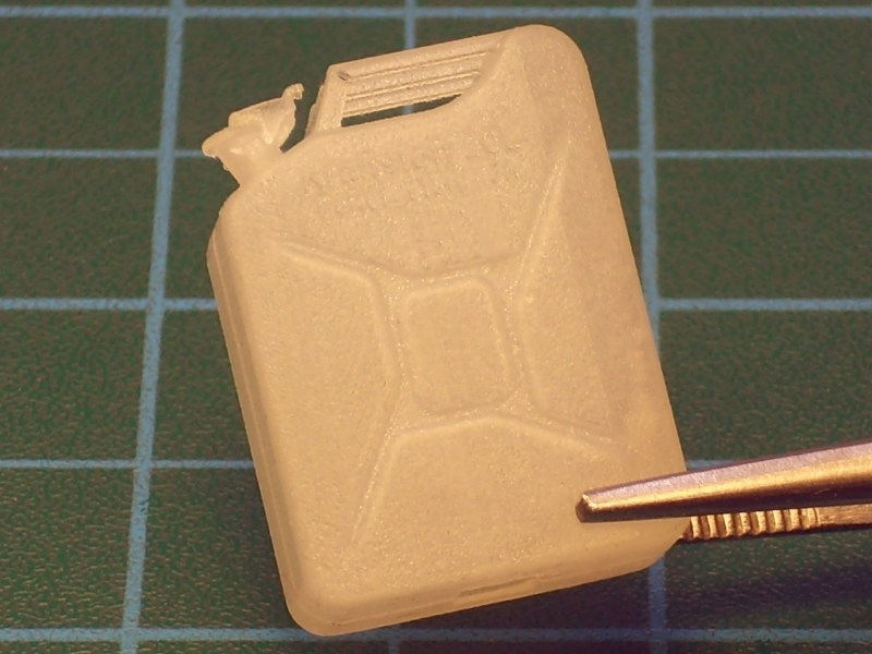
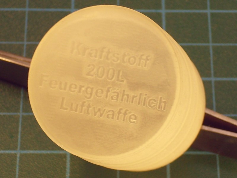 |
Mesajı Yazan: Nick_Karatzides
Mesaj Tarihi: 18/04/2016 Saat 05:11
Rotary hand pump used by techical crews & maintenance personnel to transfer fuel from the 55 gallons drums to aircraft & armoured vehicles fuel tanks or into the 20 lt fuel canisters (both drums & canisters are available for sale at http://www.anyuta3d.com - Anyuta 3D products catalogue ). This type of manual fuel pump used by Luftwaffe & Wehrmacht during WWII. The rotary hand pump kit contains all necessary parts for assembling one fuel hand pump under 1/18 scale. Any extra diorama accessories (hose, 55 gallons fuel drum etc) are not included and should be purchased separately.
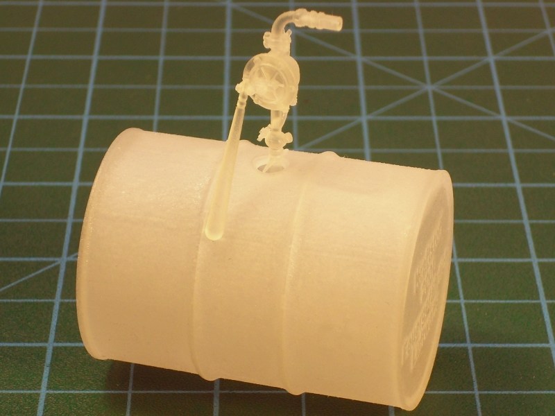
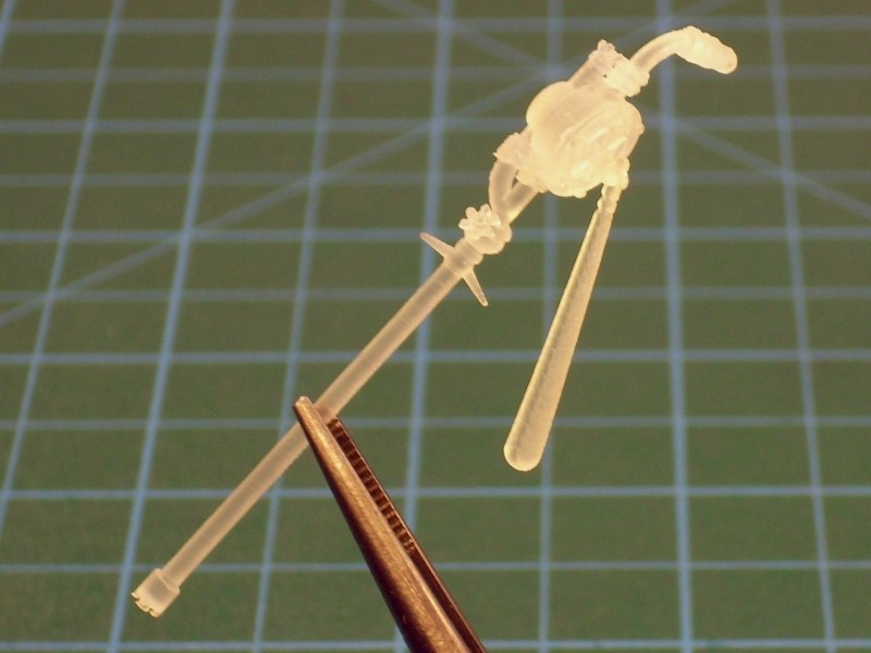
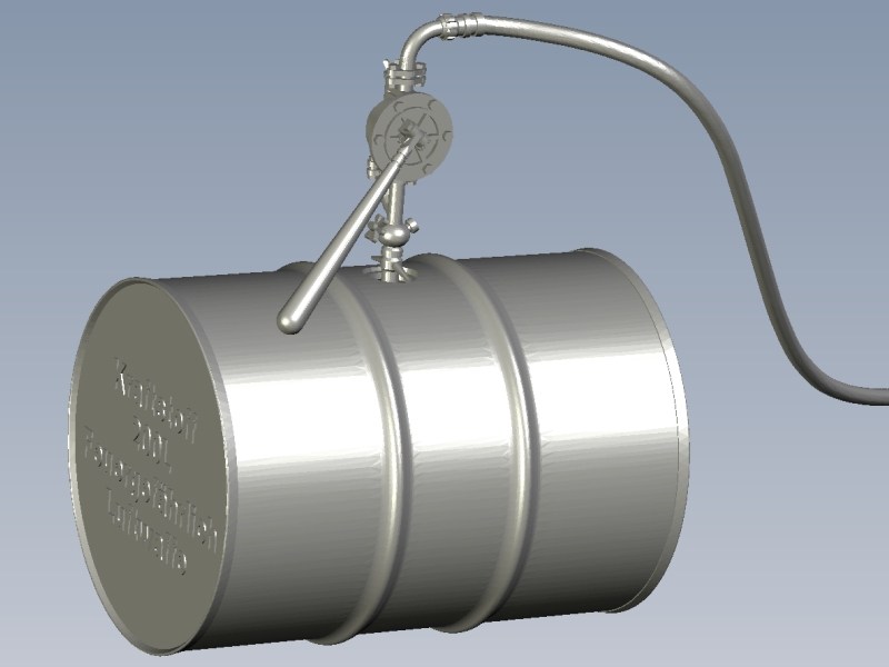
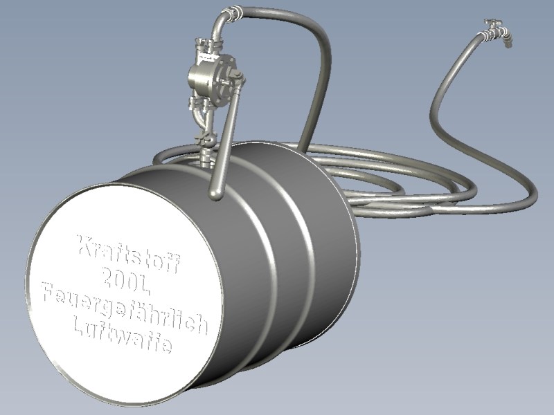
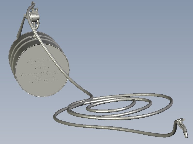
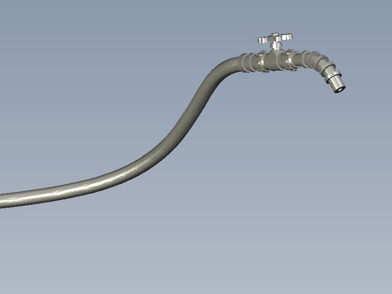
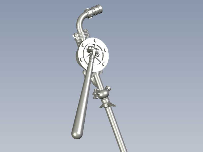
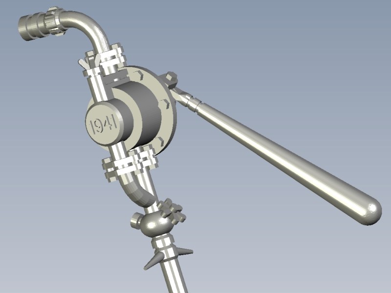 |
Mesajı Yazan: Nick_Karatzides
Mesaj Tarihi: 18/04/2016 Saat 05:15
|
Although 3D printed models do not differ so much from ordinary kits, the plastic material may cause surprises. Some of the kit parts may feel a little greasy and appeat slight traces of oil on their surface. As I've already described into previous pages, it is absolutely normal. After the 3D printing process was finished and the kit parts been removed from the printer tray to be washed into an ultrasonic oil bath and later an ultrasonic water bath, some oil traces escaped the clean inspection and dry by hand procedure. Parts can be easily cleaned by following one of the following methods:
- By washing parts with water (NEVER apply water hotter than 50º C / 125º F or you'll be really sorry) & dishwasher soap and brush gently with an old soft toothbrush. Keep in mind that items are only 0.3mm to 0.5mm thin and they are very fragile. Therefore, being very carefull while washing the parts is a necessary. - By sinking everything into a plastic bowl filled with White Spirit and leave it there for few seconds or a couple of minutes (max) to wash oil traces. In the end the the kit wont feel greasy anymore and show an almost complete white colour. Never use anything more "aggresive" than White Spirit. Also, AVOID stove cleaning spray and acetone nail polish remover products - both clean oil & wax but also dissolve the plastic leading to breakage and failure. - By using hydrosonic cleaning machine (IMHO, is the best alternative), filled with water & dishwasher soap and repeat procedure if needed. Meanwhile the water will turn cloudy - thats the wax. It is of utmost importance that the model parts are properly degreased - otherwise the paint will not stick. Small remainders can be removed with a swab or toothpick. For my own 1/18 scale Kolibri cutaway model kit, I decided (since I do not have a hydrosonic cleaning machine) to wash slight oil traces on parts by sinking everything into a 2 litres plastic bowl filled with White Spirit and leave it there for a couple of minutes. Shortly after all kit parts enjoyed their bath into a White Spirit filled bowl, they were washed with liquid soap & warm water, placed on soft paper towels and allowed to dry. 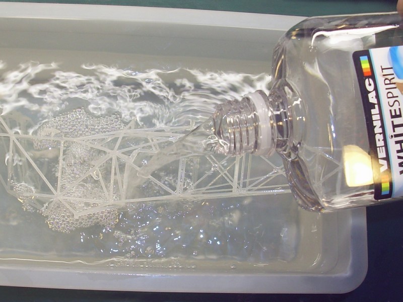
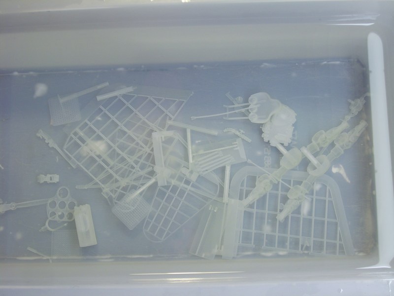
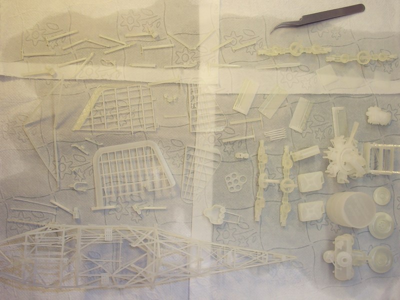 |
Mesajı Yazan: Nick_Karatzides
Mesaj Tarihi: 18/04/2016 Saat 05:19
After all kit parts washed in White Spirit & water to clean the oil traces, every section of the model has been repeatedly dry fit tested to ensure that all individual parts could be later combined together as an overall built model. When looked OK to me, each part sprayed over with an undercoat mixture of 80% Life Color LC02 Matt Black and 20% Life Color LC37 Matt Burnt Umber acrylic, to prepare the surfaces for the basic paint which about to follow. Later, a very thin coat of Life Color UA503 Light Blue acrylic paint layer applied, very diluted with Life Colors acrylic thinner in a 30% paint to 70% thinner ratio. The darkest recesses sprayed first, gradually working my way up the frame, keeping to the lighter areas on central parts of each tubular part. Same pattern maintained throughout the entire painting process to preserve continuity with the light source and subsequent spraying sessions continued to utilize very thin Life Color UA503 Light Blue acrylic paint layers as a base to varying degrees because it is the source of the light colour.
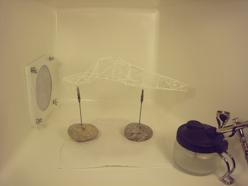 The tubular frame got gradually lighten with each successive layer as the painting process continued, so the second layer of paint as the medium layer of the base coat, is based upon a less diluted 50% paint to 50% thinner ratio. Then, I added just a few drops of Life Color LC01 Matt White FS37925 acrylic paint into the mixture to lighten up this stage of paint application, being very careful to always follow the established gradation pattern, untill contrast between light and dark started to become apparent. 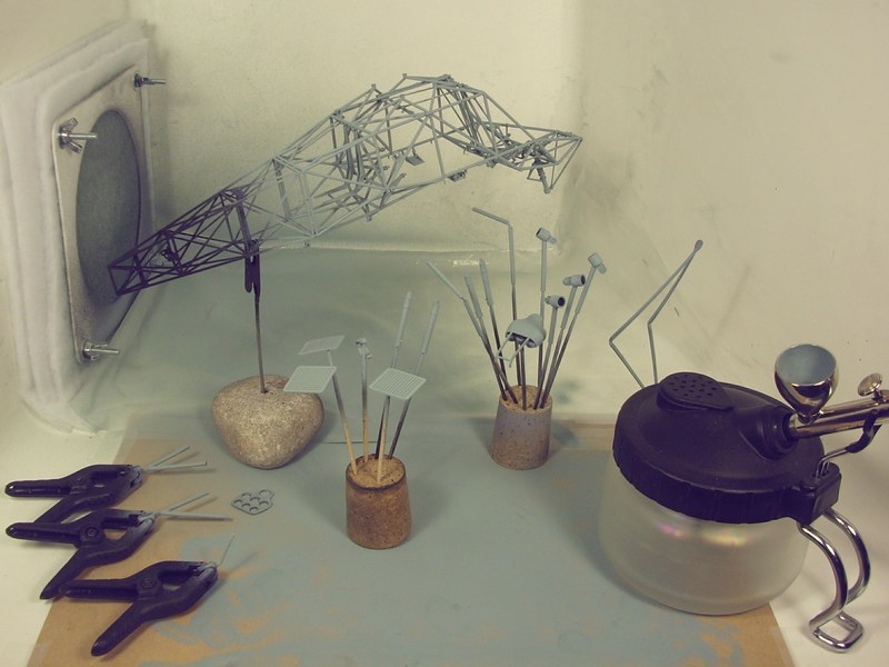 |
Mesajı Yazan: Nick_Karatzides
Mesaj Tarihi: 16/11/2016 Saat 12:10
|
As soon as most individual 3D printed parts on both http://shpws.me/KdjE - full fuselage & http://shpws.me/L3F4 - cutaway scale model kit versions were already painted & weathered, everything should be combined and assembled as an overall built miniature. Having already installed the rudder fin and the two horizontial elevator fins on the http://shpws.me/KdjE - full fuselage version models tail, the gear box unit was next. Following instructions described into the building manual (click http://www.pdf-archive.com/2015/11/14/1-18-scale-flettner-fl-282-v21-kolibri-instructions/1-18-scale-flettner-fl-282-v21-kolibri-instructions.pdf - HERE for the PDF formated file) through pages 33 to 37, all the four pins on gearbox unit should be simultaneously aligned onto the upper frames slots and same time linked downwards with engines transmission shaft, as shown on following pictures. 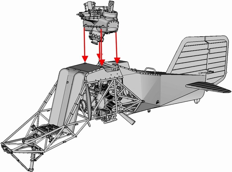
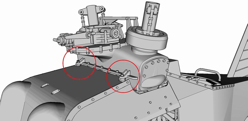 Here is a detailed view of the correctly installed gearbox unit as seen underneath the fuselage cover. Notice that the forementioned gearbox unit is linked (marked with red circle) with previously assembled engines transmission through a shaft coupling. 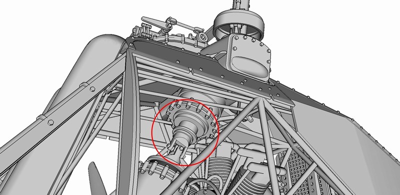 This is how the assembled block of rotary engine, transmission unit, cooling twin blade propeler fan, drive shaft & upper gearbox unit should look like when correctly fit into each other. Notice that tubular frame is not visible here for better example view. 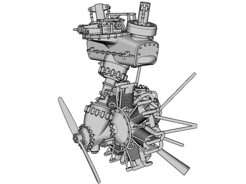 Both http://shpws.me/KdjE - full fuselage & http://shpws.me/L3F4 - cutaway scale model kit versions are equiped with fixed non-retractable tricycle type undercarriage with a steerable nose. The tubular shaped struts & the central supporting section anchoring points aligned on proper U-shaped slots found on the lower fuselage area. Following instructions described into the building manual, the upper & lower anchoring points on each tubular landing gear strut end should be simultaneously aligned onto the tube frames U-shaped slot (marked with red arrows). Successful assembly of main landing gear section will positively affect process to follow - a side tilted helicopter model, would look completely unreal. 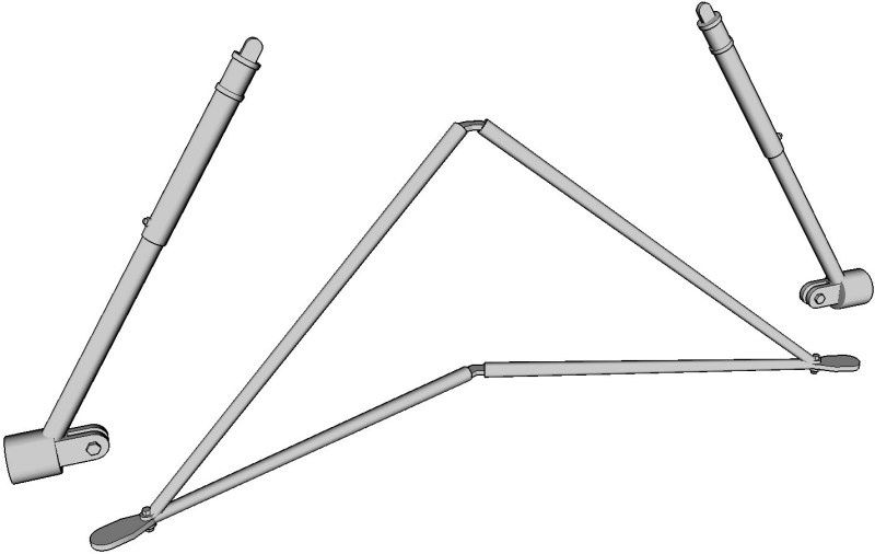
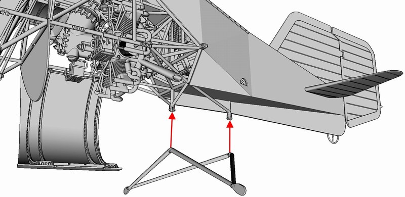
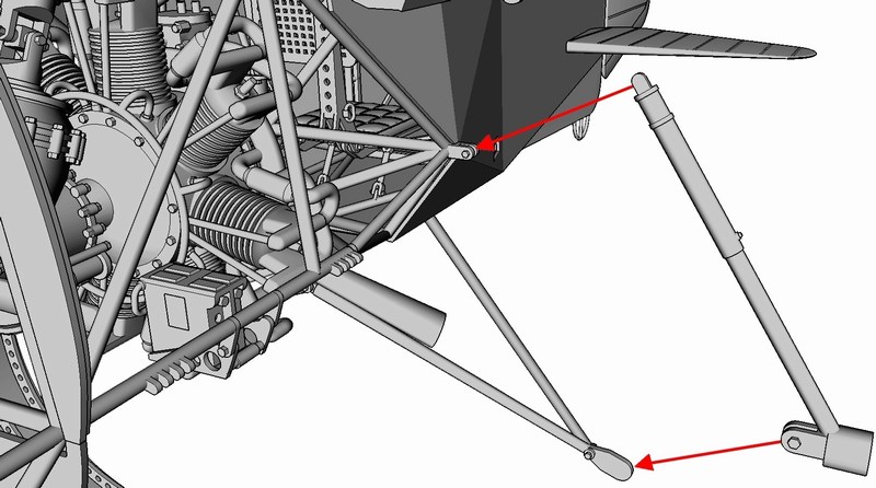 This is how the fixed non-retractable tricycle type undercarriage frame should look like when the parts correctly installed on the fuselage frame. Everything secured in place with a drop of cyanoacrylate super glue. 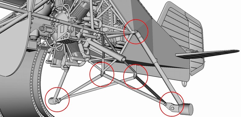 To add some weathered look on fuselage areas (doped fabric covering over the steel & wooden frame on real helicopter) and replicate parts like being dirty, dusty or sunfaded, I appplied different shades of dark brownish pigment powder, trying to blend them nicely to look artistically accepted and create 3D-alike effects on flat surfaces. The results on model may not look so strictly realistic comparing to the real world objects, but IMHO scale modeling has to balance between realism factor and artistic expression. I admit that adding (extensively in some specific areas) pigment powder, may not accurately replicate the reality, but it looks artistically attractive and becomes easily accepted by visual subconscious. 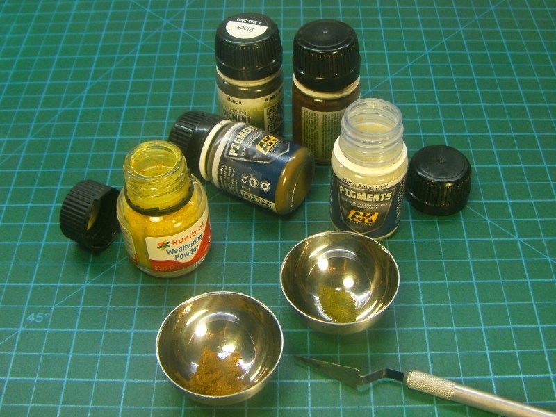
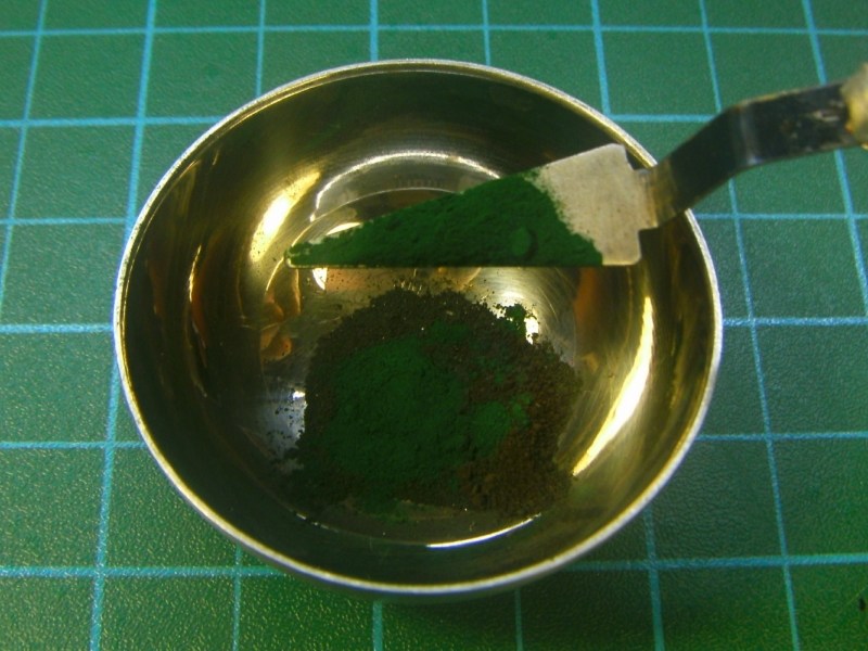
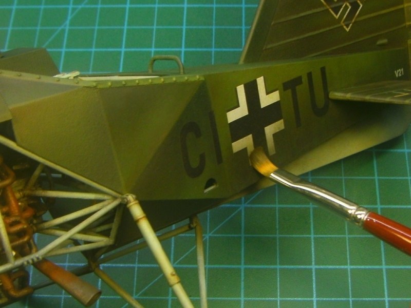
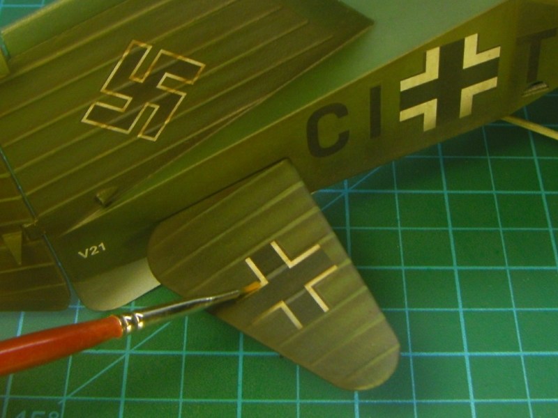 The main advantage of the pigment powder shades is that the already painted scale model gets some nice weathering / lighting effect tones. On the other hand, the big disadvantage is that once the pigment powder settles on the models surface, it should not be touched to avoid smudging. To overcome this problem, modelers usually secure the pigment in place by carefully soaking the model surface with modeling fixer. However, even after applying modeling fixer, it is not absolutely safe to touch the model. 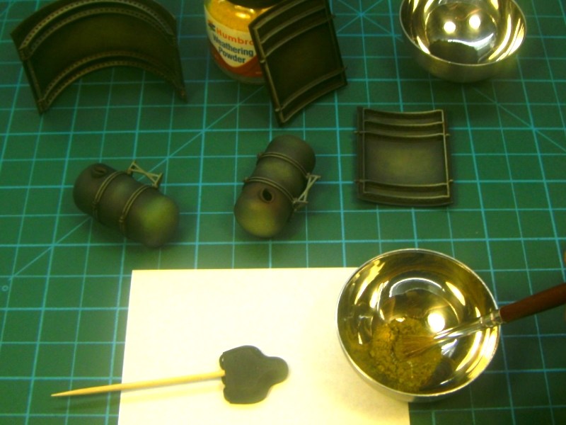
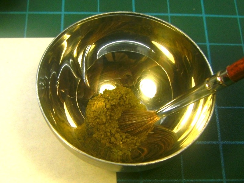
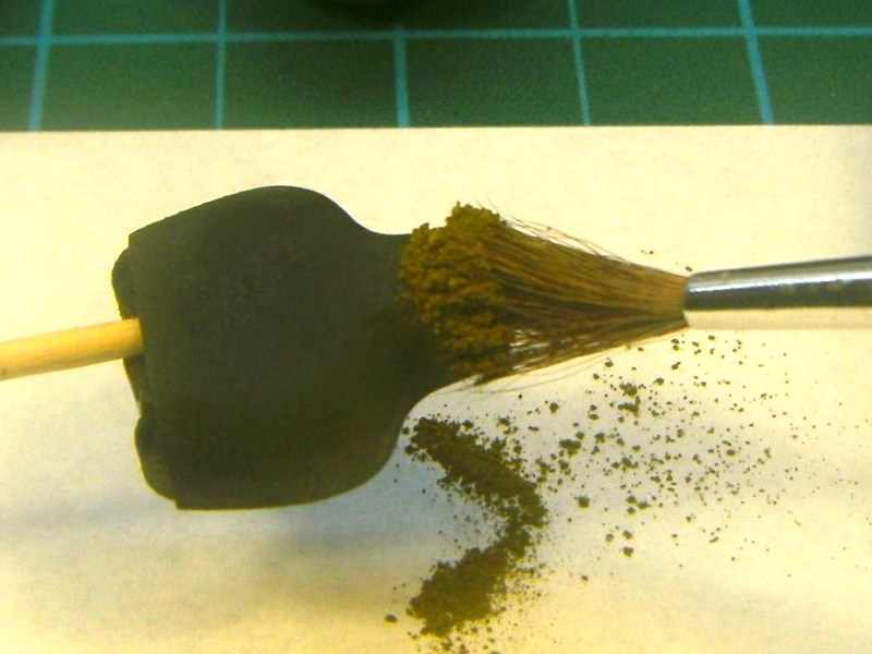
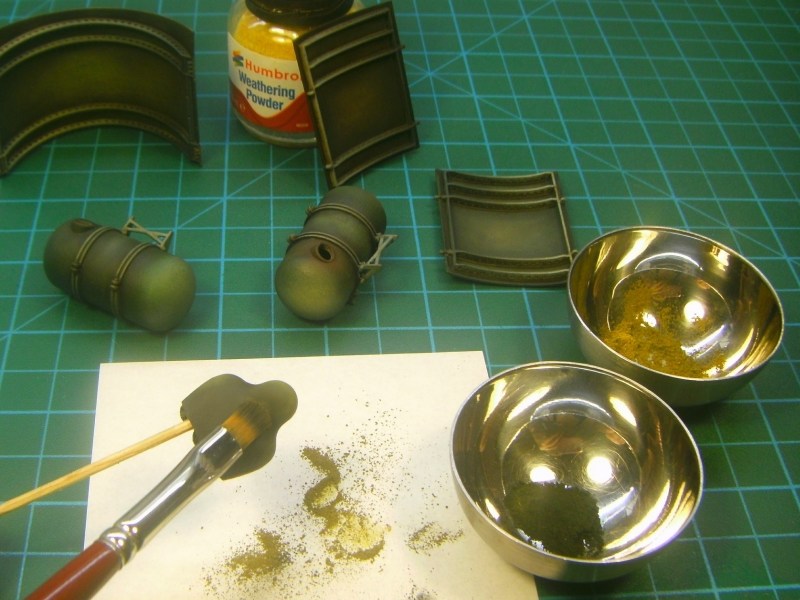 I tried a different approach and used Winsor & Newtons fixative for charcoal & pastels (instead of modeling fixer) over pigments. Although similar, the Winsor & Newtons fixative is different from the modeling fixer. The Winsor & Newtons fixative solution (available in 75ml and 500ml bottles) provides protection of charcoal, pencil, pastel & chalk drawings - it is mostly used by painters & pastel artists to seal the final result of their work. Although the model paint gets glossy after Winsor & Newtons fixative applying, the good news is that model can be sprayed over with final matte coat after securing pigments with Winsor & Newtons fixative, without leaving disastrous spots or milky stains on model (as usually happens when applying matte coat over modeling fixer-sealed pigments). 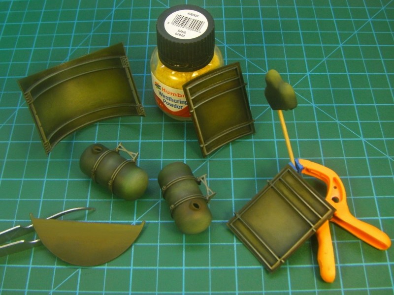 Once the Winsor & Newtons fixative dried, the (glossy) outcome had tonality differences because pigments applied earlier and looked like been faded by the sun, fouled by dust and stained by fuel & oil. As previously mentioned, the glossy look is not actually a problem, since the model can be sprayed over with final matte coat later, while keeping all the pigment shades. 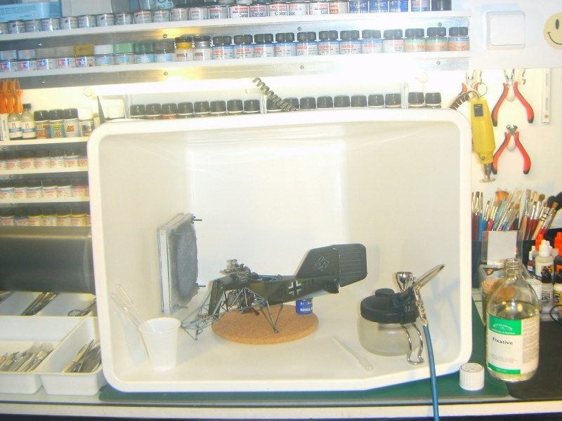
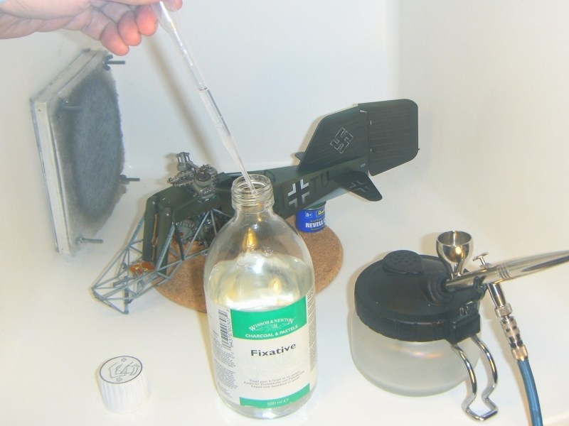
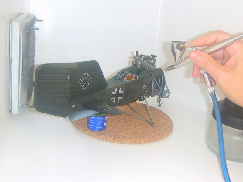
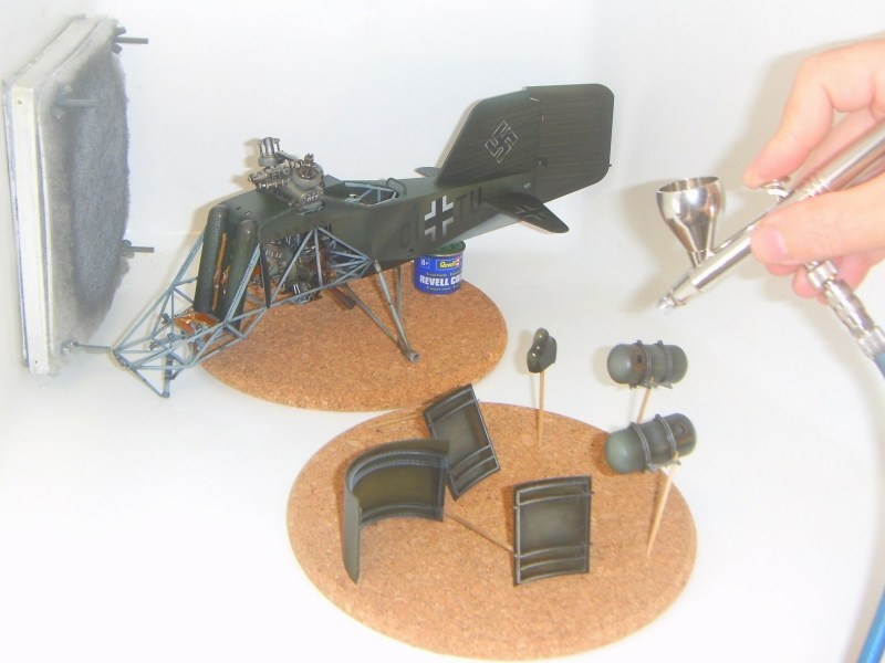
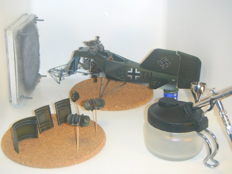 The wheels attached on undercarriage, according instructions described into the building manual. The U-shaped nose wheel supporting fork, pinned into the shock absorber slot while making sure that axes are aligned, as shown in following picture. Notice that nose wheel is tilted accordingly to the rudder fin (which is already installed) as previously explained. 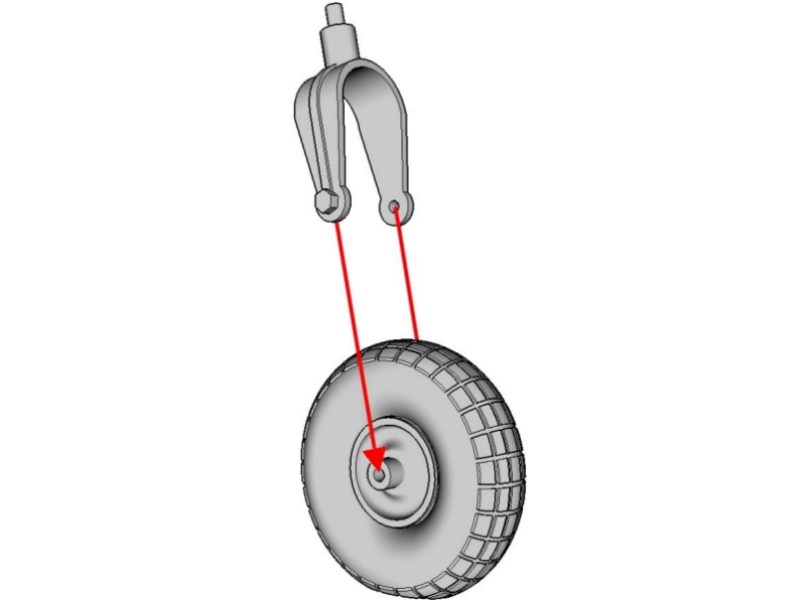
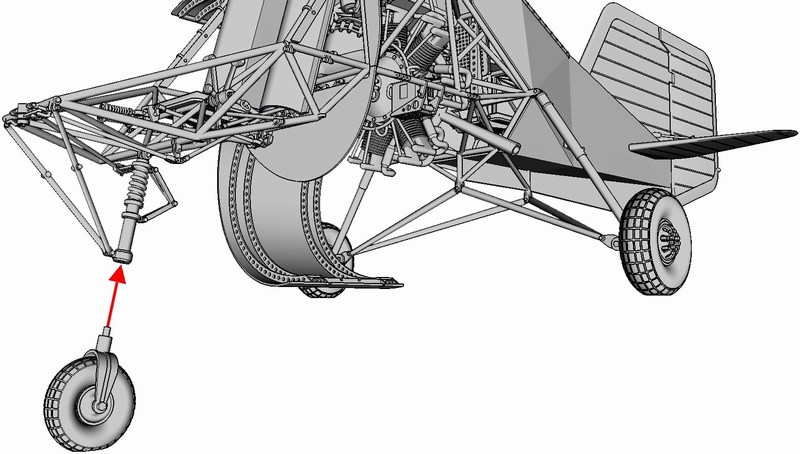 The twin 25 litres cylindrical fuel tanks (mounted externally on both sides of the pilot seat), attached on frame by plugging pins into proper slots as shown on the following pictures & secured in place with cyanoacrylate super glue. Since these cylindrical fuel tanks are made hollow, the sealing caps can be removed if building a refueling diorama scene. Notice the details marked into the red circles - this is how the cylindrical external fuel tanks should look like when correctly mounted externally on both sides of the cockpit area framework. 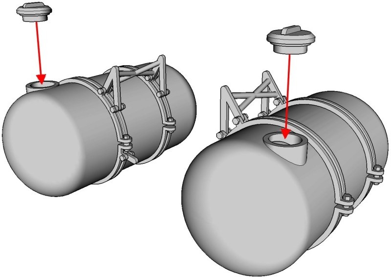
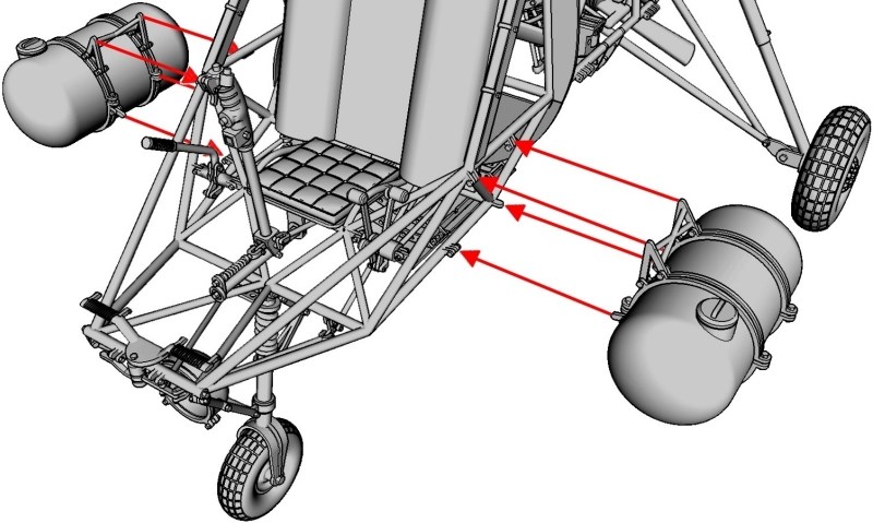
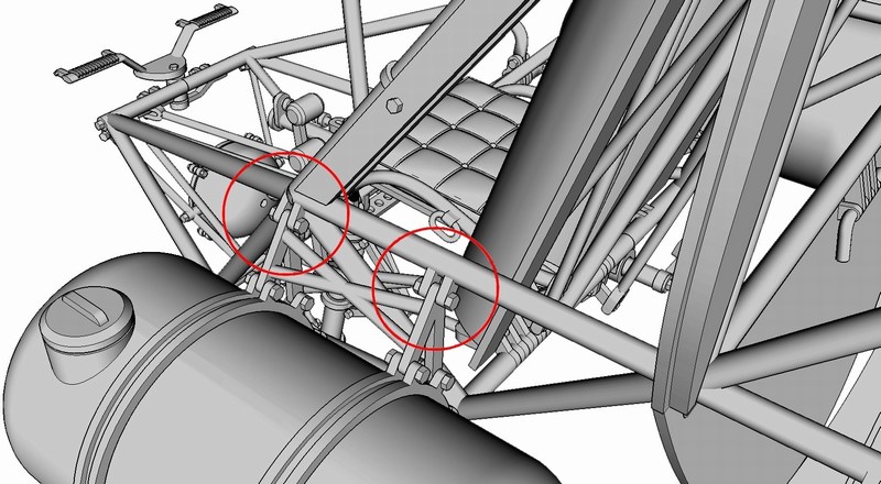 Here is how a semi-built http://shpws.me/KdjE - full fuselage scale model kit version looks like as seen underneath, after few of the kit parts installed. More parts such as the side & lower fuselage door panels, the rudder pedals & control levers in cockpit area, the instruments panel, the rotor heads & blades etc, will be attached on main frame later. 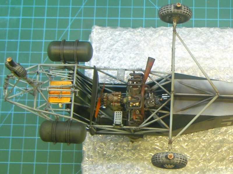
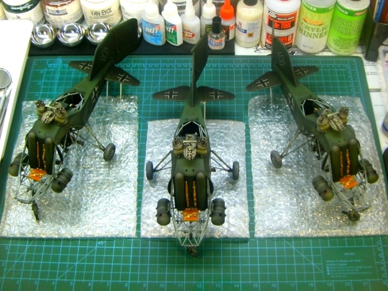 |
Mesajı Yazan: Nick_Karatzides
Mesaj Tarihi: 16/11/2016 Saat 12:10
|
When I started this Kolibri project for a collector located in Kiel, Germany and later built more identical helicopters for other customers and my own collection at home too, I was concerned about a proper display option, on which the model would be placed. My goal is to build up a simple diorama scene, which looks like a maintenance & refueling area on a forwarded airfield. From an artistic point of view, a maintenance & refueling area scene might possibly dictate everything to be into a state of complete engine oil n grease messiness. My goal is to keep the Kolibri helicopter as protagonist into the scene, while filling the empty space with few maintenance & refueling area related items, to maintain a visual balance. What I am actually trying to present here, is an intentional setup to show scale models details through opened maintenance panels, opened hatches, removed engine unit etc without extreme diorama action, nothing that could possibly distract viewers attention from the Kolibri helicopter which is always the main protagonist of the story. Any other item should be standing as an uninvolved walkon to simply complete the directorial picture. 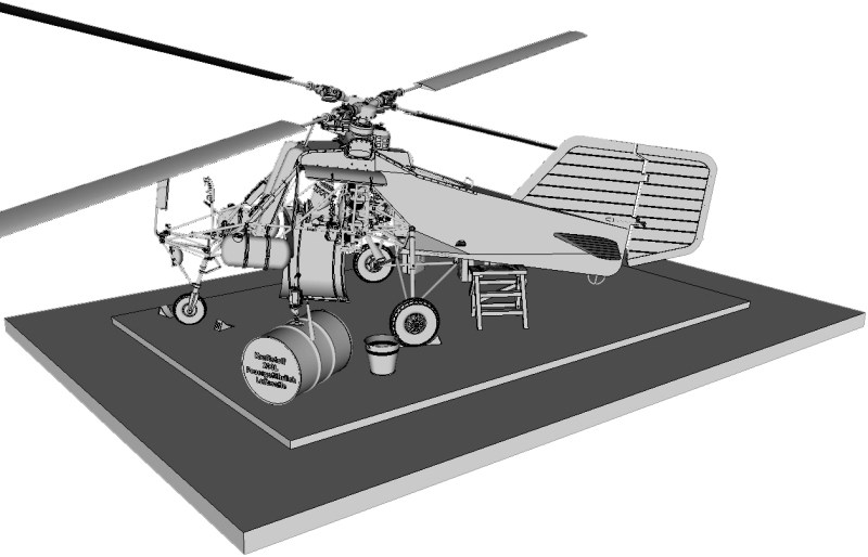 While scale model painting was underway, I thought as good idea to place the Kolibri helicopter scene on a grass airfield area. My opinion had been probably shaped (aka influenced) by viewing WWII era pictures, where the Flettner Fl-282 V21 Kolibris were stationed on the fresh green grass. Unfortunatelly, the problem that would arise from such a choice, is that the (already painted green) helicopter would be visually lost into this greenish backround. Due this reason, the idea of placing the Kolibri model on grass abandoned and the idea of a concrete covered airfield apron area (with just a few short grass sprouted between concrete slabs) where pre-flight activities were done, seemed much better. The scene would require at least a 450 x 350mm display base, considering that helicopter measures approx 357mm long and 138mm wide, without counting the rotor blades with disc diameter approx 700mm each. Those who have read my previously uploaded projects, might remember that I prefer using plaster powder to build the section that recreates the ground, especially if it is asphalt. However, the 450 x 350mm dimensions of the scene dictate plaster quantity more (and therefore heavier) than usual and for this reason I chose to use another material, because the goal was to build a airfield display base instead of weightlifting equipment for champs. For this reason, I decided to follow a different way, by replicating concrete covered airfield apron with cork sheet. I purchased two 500 x 500mm sized & 4mm thick sheets of cork from my local hobby shop, which I cut & shaped around with my Black & Decker 400W / 3000spm jigsaw. The basic idea, is to build an approx 8mm thick & flat surface which protrudes above the polished wood display base, on which short vegetation (grew between the concrete slabs) and diorama accessories (such as maintenance tools, fuel canisters etc), will be added later. 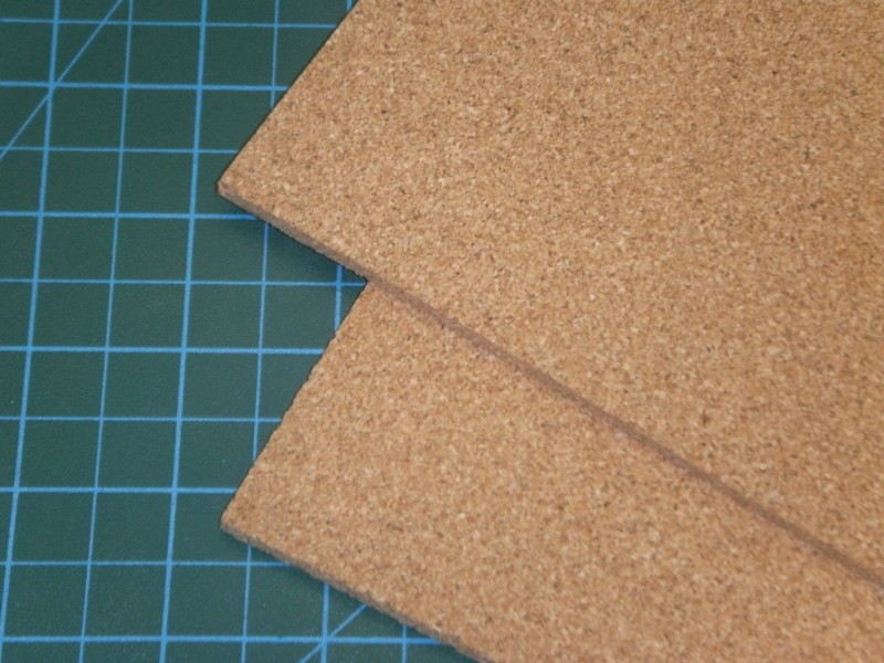 As soon as the 4mm thick sheets of cork identically cut into shape, sandwitch glued and the concrete plaques were lined, I used my airbrush to paint it. As I usually like to do, three different acrylic paint layers were applied on the concrete apron surface. First, mat black colour covered the area and then lighter greyish and earth layers applied, while airbrushing in almost zero degrees angle, to let the darker areas between the concrete plaques remain naturally dark. 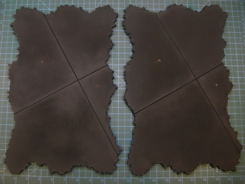 The concrete apron surface was paint with different greyish & earth tones and as soon as the acrylic colours dried, I tried some drybrushing on selected spots using sand tones. Concrete areas on which the oil drums, the fuel canisters, the under maintenance radial engine etc will be placed later (probably resulting oil & fuel stains on ground), painted differently with more yellowish shades to replicate sawdust spread to absorb leaked oil & fuel. As for the vegetation that grew between the concrete slabs, I used some http://www.heki-kittler.de - Heki static grass, secured in place with water based white glue for wood which becomes transparent when it dries. When it looked OK to me, I sprayed over with Humbrol enamel matte coat, to seal the paint & vegetation result so far and left it overnight to dry. 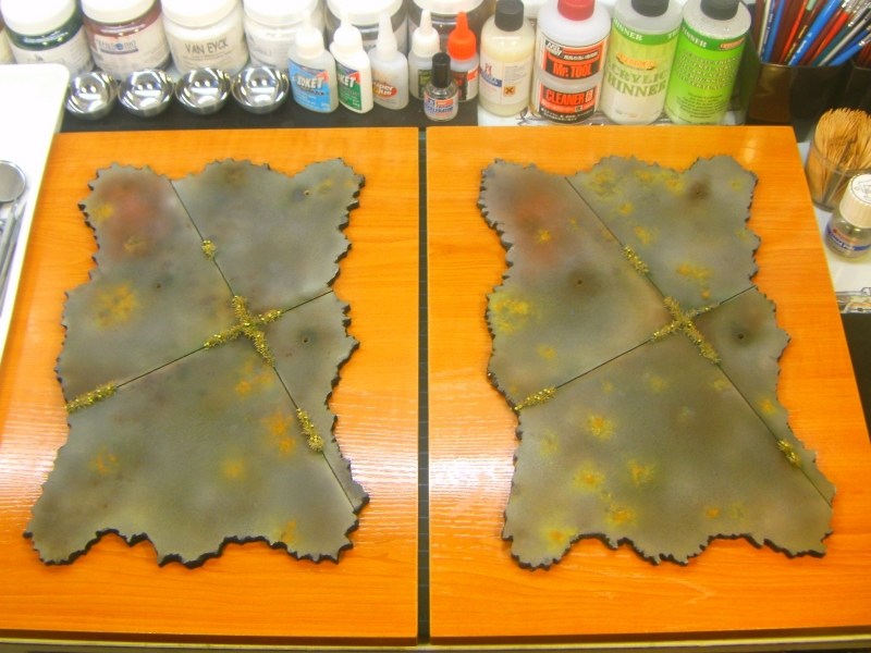 Meanwhile, some of the earlier described 3D printed items (unrelated to the helicopter structure) such as few http://shpws.me/KeaD - 1/18 scale 20 litres fuel canisters , one of these http://shpws.me/MVIv - 1/18 scale 55 gallons oil drums and one of these http://shpws.me/KeeV - 1/18 scale 200 litres fuel drums as used by Wehrmacht, Luftwaffe & Kriegsmarine during WWII with Kraftstoff 200L Feuergefährlich Luftwaffe & Kraftstoff 20L Feuergefährlich 1941 inscriptions engraved or embossed on side, also got some paint, dirt & weather effects. All the above mentioned diorama accessories are listed into http://www.anyuta3d.com - Anyuta 3D products catalog and available for sale under various scales and sizes. 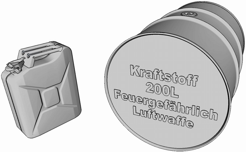 The previously mentioned 1/18 scale 200 litres fuel drum received a basic layer of Life Color UA505 RLM 79 Sandgelb II / Sand Gold II acrylic paint and the 1/18 scale 55 gallons oil drum painted with Life Color UA504 RLM 02 Grau / Grey acrylic paint and allowed to dry overnight. 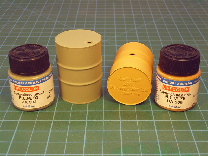 Once the acrylic base coat has cured, both drums got some weathering, paint scratches and rusty chipping effects while using the sponge technique to give visual interest to the base colour. To achieve best results, I did use a fine textured sponge like those used for packing of electrical items. Fresh rust marks also added in some selected points, with some of the Life Color UA704 Rust Light Shadow 2 acrylic. Using a fine tipped brush, the Light Rust Brown & Dark Rust oil paints by 502 Abteilung & AK Interactive series painted in vertical lines from various chips and scratches added earlier. Once the oil paints had been allowed to dry for a short while, a brush dampered in White Spirit used to blend and soften these streaks for a more subtle effect and obtain visible signs of wear & oxidation. 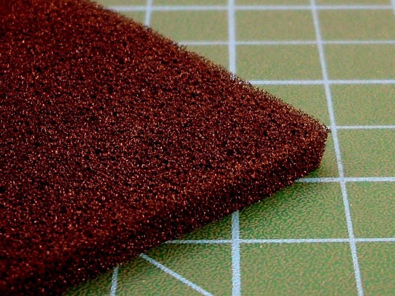
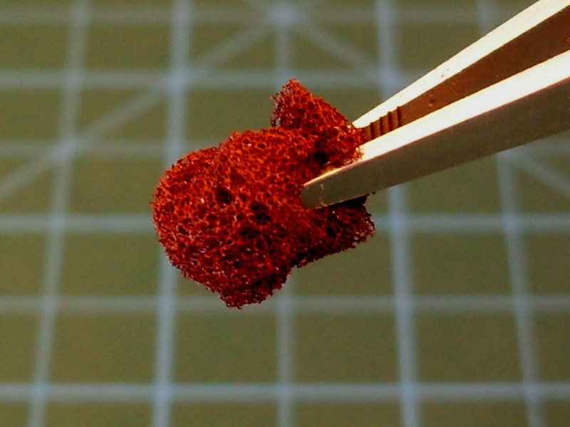
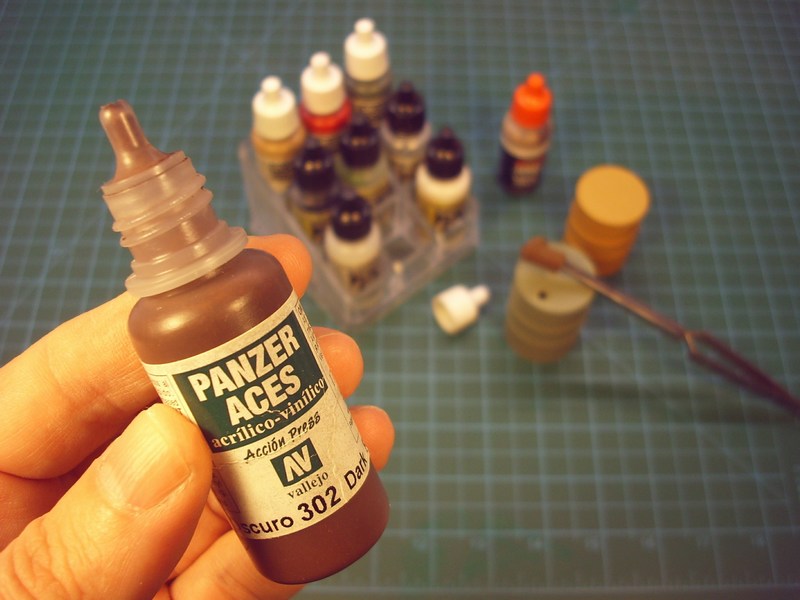
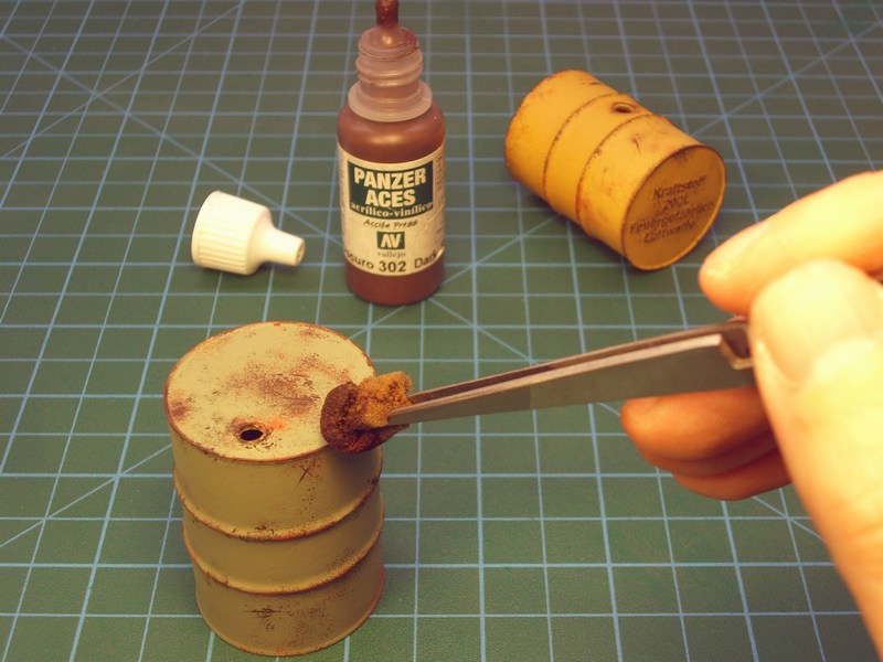 |
Mesajı Yazan: Nick_Karatzides
Mesaj Tarihi: 17/11/2016 Saat 14:35
|
The helicopter model secured in place, by wedging the pins under the wheels into holes that had been already opened on concrete (that's the reason wheels had pins underneath). Once the Kolibri placed on display, each one of all these previously mentioned 1/18 scale items & diorama accessories also secured on ground with hidden metal pins and glued with transparent silicon. Finally, few more maintenance & refueling area related items (such as one http://shpws.me/MuYa - 1/18 scale WWII era fuel hand pump , a set of http://shpws.me/MvVq - 1/18 scale wheel chocks , some http://shpws.me/MBkD - 1/18 scale wooden crates and a couple of http://shpws.me/MBpl - 1/18 scale water buckets ) also prepared to be placed on concrete display base. A last moments addition, an also 3D printed http://shpws.me/Mq3f - 1/18 scale WWII era Fahrrade M30 reconnaissance duty bicycle model, prepared for the diorama display.
All the above mentioned diorama accessories are listed into http://www.anyuta3d.com - Anyuta 3D products catalog and available for sale under various scales and sizes. 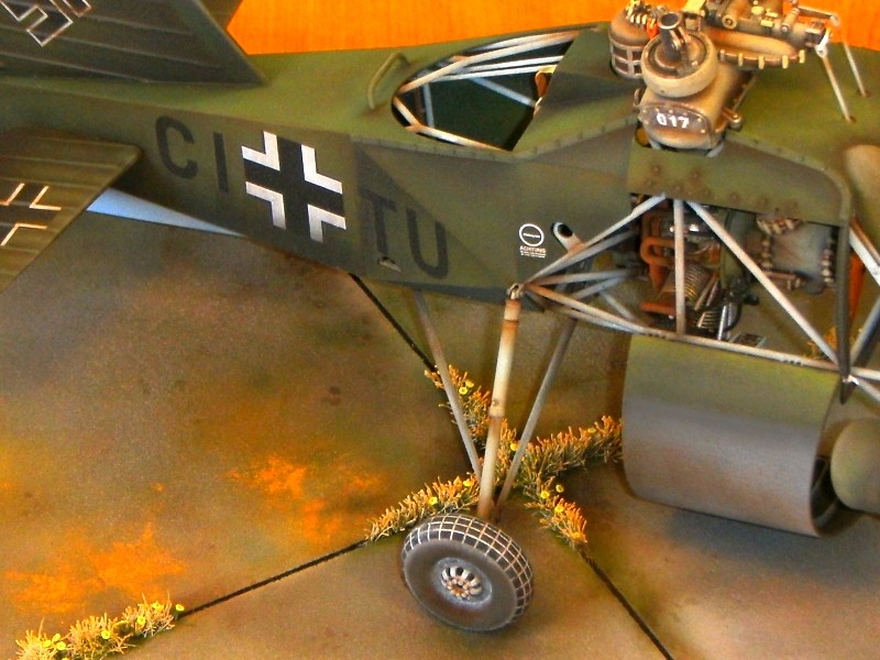
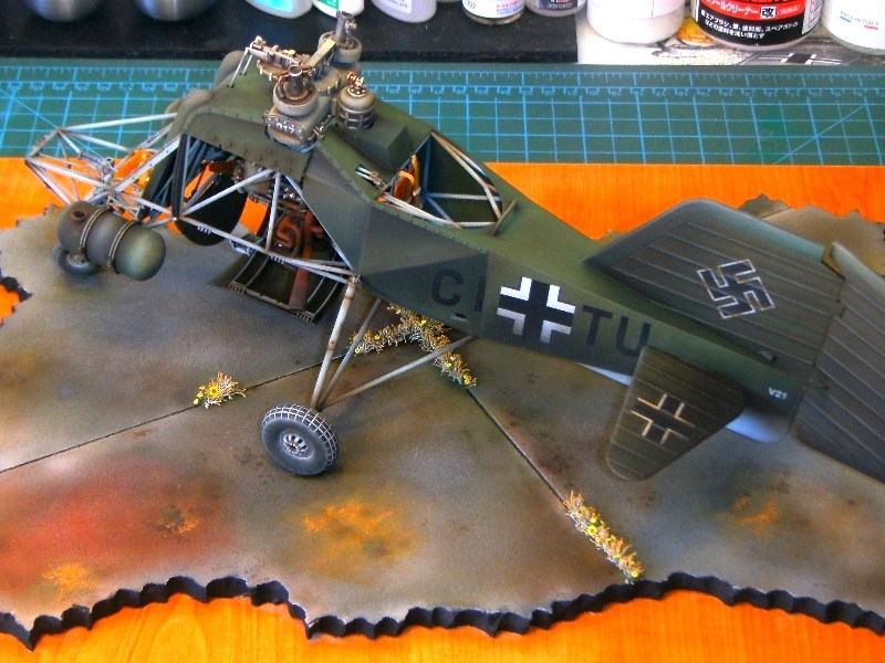
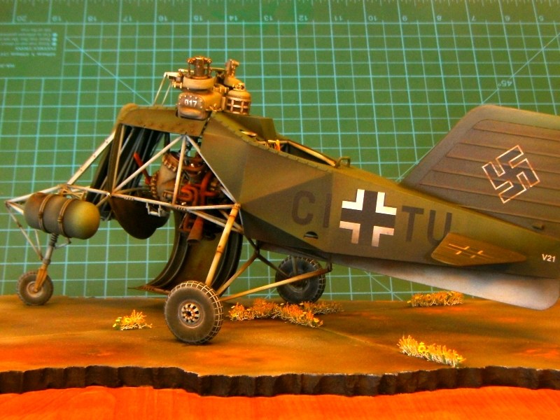
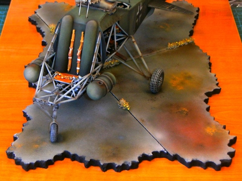
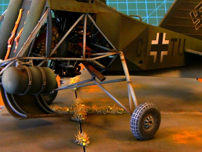
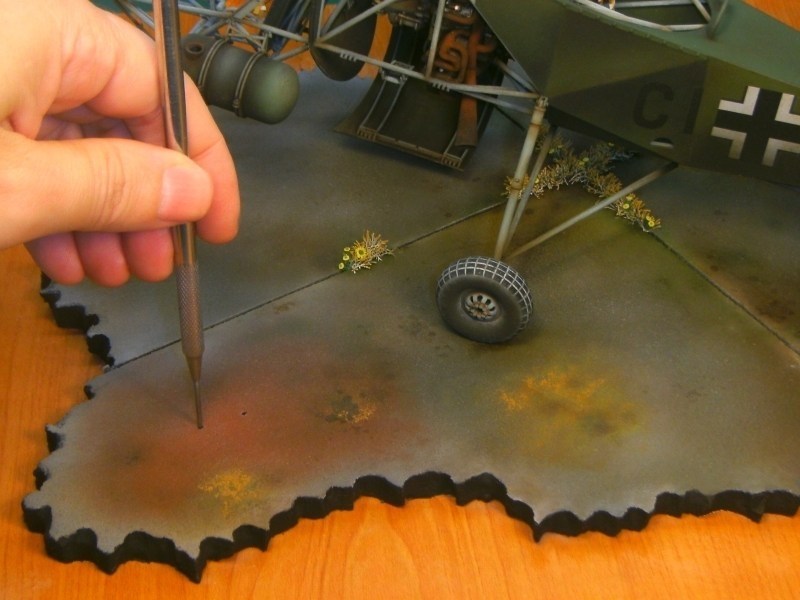
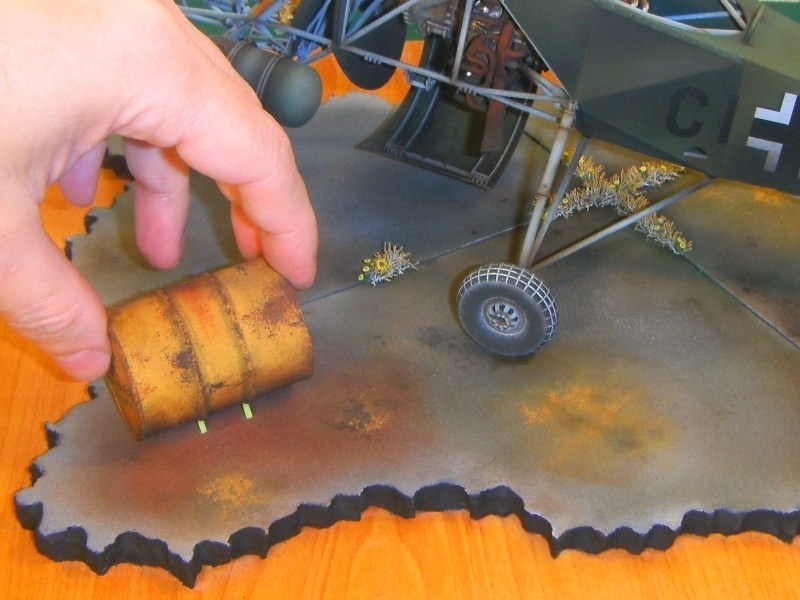 |
Mesajı Yazan: Jolly Roger
Mesaj Tarihi: 28/11/2016 Saat 19:53
|
There are times I am honestly speechless. All I can say is that I am not a fan of the colours you used on the apron and the shading on the crosses are a tat much but hey, that is my personal view. Superb work. ------------- Consume Ergo Sum |
Mesajı Yazan: Nick_Karatzides
Mesaj Tarihi: 27/07/2018 Saat 12:44
|
Been long time since last visit, huh? Well, let's remember some hobby fun again. :)
The objective is to build two different diorama scenes for two different versions of the same helicopter: - One for the https://www.shapeways.com/product/VTUAS9MD4/1-18-scale-flettner-fl-282-v21-kolibri-model-kit - full fuselage version of the 1/18 scale Flettner Fl-282 V21 Kolibri model kit and, - A second for the https://www.shapeways.com/product/TUYFDD2EB/1-18-scale-flettner-fl-282-v21-kolibri-cutaway-kit - cutaway / fabric stripped version of the 1/18 scale Flettner Fl-282 V21 Kolibri model kit . According to plan, both of them would include few additional features without distracting viewer's attention, keeping the Kolibri helicopter as the main protagonist of the story. Starting with the full fuselage version, the addition of a WWII era Luftwaffe's 200 litres fuel drum with a handpump attached, few 20 litres canisters and a filled bucket left on ground, seemed good idea to me in order to present a short refueling scene. 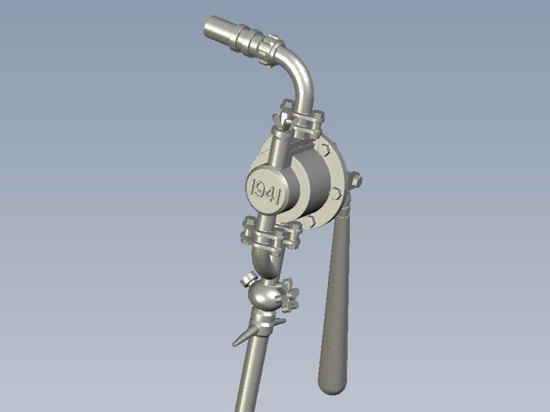
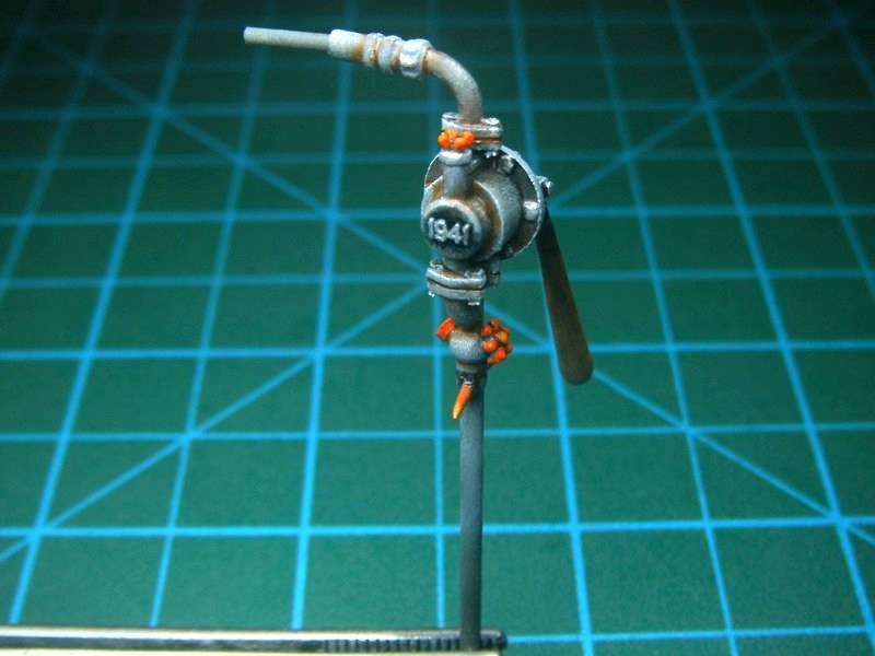
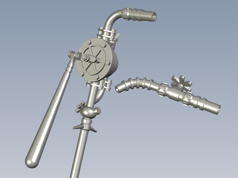
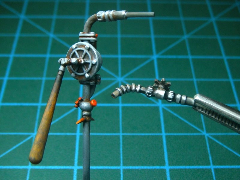
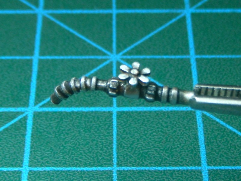
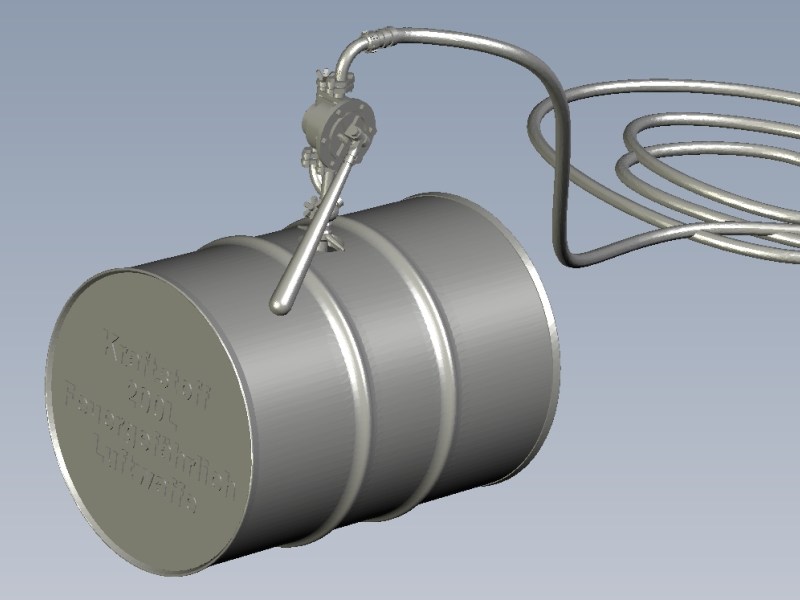
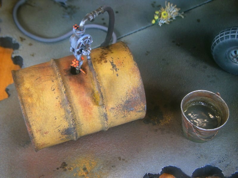
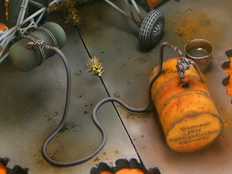
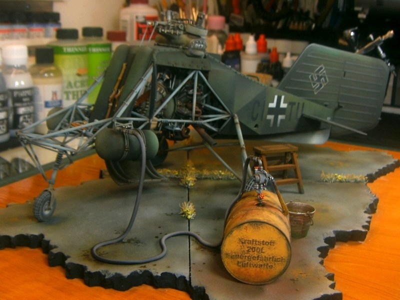
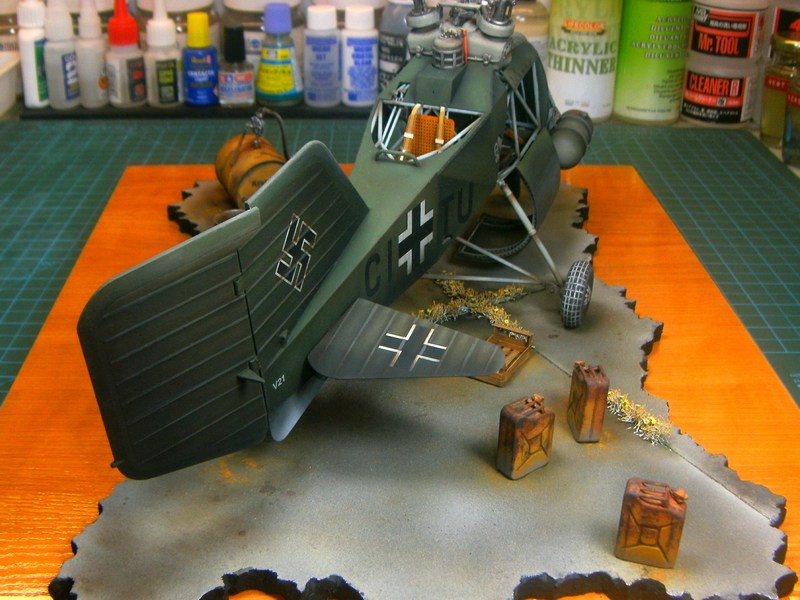 Rivet counters may say that the presence of a 200 litres fuel drum right next to the helicopter may look unreal or too much. Well, considering that the twin seat Fl-282 V21 helicopter had two 25 litres cylindrical fuel tanks mounted externally on both sides of the pilot seat (while the main 105 litres fuel tank installed on previous versions removed to host observers rear seat), a number of only 2 or 3 fuel canisters could be just enough to do the job. I am not sure about the official refueling procedures followed by Luftwaffe for the Kolibri helicopter during operational conditions & which were the appropriate method followed by engineers & maintenance personnel. - Did they park the Kolibri close to area where 200 litres fuel drums stored and later pumped fuel directly into helicopters tanks through a hose? - Did they move (carrying on a truck / cart) the 200 litres fuel drums next to the helicopters parking area and later pump fuel inside tanks? - Did they fill helicopters tanks with hand-carried smaller 20 litres canisters & funnels, brought from main fuel storage area, next to parked Kolibri? IMHO, all the above (and many others) sound quite possible scenarios. Since we all have seen WWII era pics showing airfield ground personnel using a big variety of methods, from operating Opel refueling trucks, to mule / donkey driven carts or poor maintenance personnel carrying 20 litres canisters by hands, I think that having few 20 litres canisters left into the diorama scene and same time a 200 litres fuel drum feeding the helicopter tanks directly through a hose, could be considered as realistic and not just an artistic accepted option. 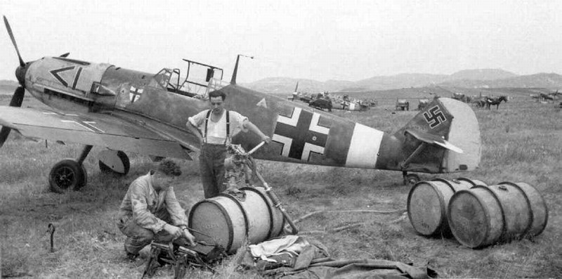
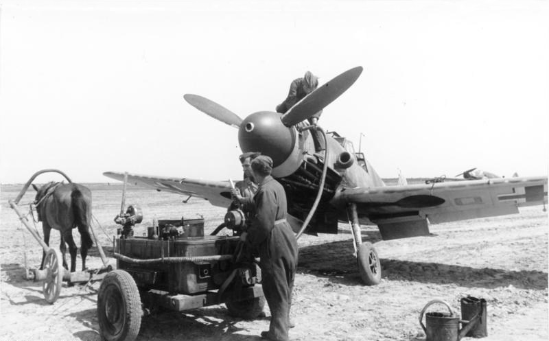
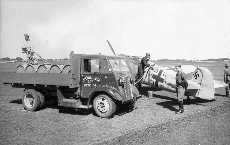 Meanwhile, the rotor blades for both versions attached on their rotor heads as described into the building manual (click http://www.pdf-archive.com/2015/11/14/1-18-scale-flettner-fl-282-v21-kolibri-instructions/1-18-scale-flettner-fl-282-v21-kolibri-instructions.pdf - HERE for the PDF formated file) through pages #88 to #94. Parts sprayed over with AK interactive AK768 primer to spot mistakes and prepare for paintjob. I did a visual inspection and shot some pictures. 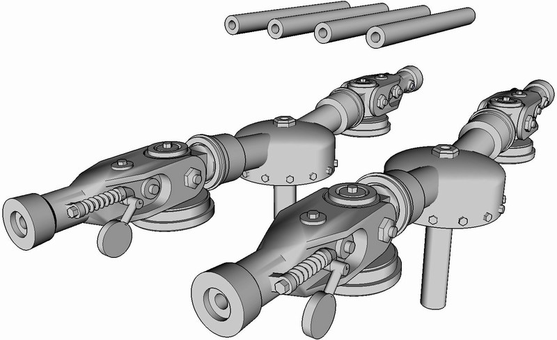
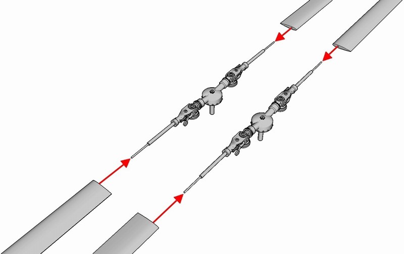
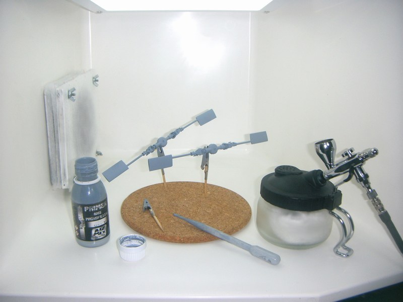
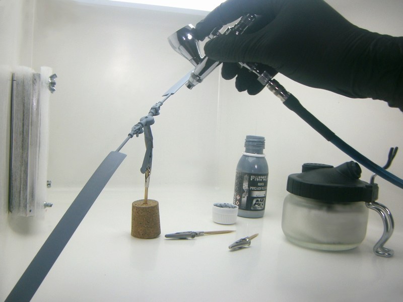 After overall primer, rotor blades dry fit tested to ensure that all individual components could be later combined together as an overall built model. I admit that its not easy to handle Kolibri scale model and find best angle for photoshoot on bench, while having the rotor blades (measuring approx 70 cm from one wingtip to the other) attached. 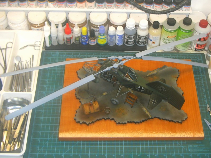 |