
 Aktif Konular
  Üye Listesi
  Takvim
  Arama
Arama |
Aktif Konular Üye Listesi Takvim Arama |
| |
| Tayyareler | |
| |
  |
| Sayfa 2 Sonraki >> |
| Yazar | Mesaj |
|
Nick_Karatzides
Üye 

Kayıt Tarihi: 06/06/2009 Aktif Durum: Aktif Değil Gönderilenler: 250 |
  Konu: 1/18 scale Instytucie Szybownictwa IS-A Salamandra Konu: 1/18 scale Instytucie Szybownictwa IS-A SalamandraGönderim Zamanı: 06/06/2013 Saat 22:41 |
|
The text following is to describe the 1/18 scale Instytucie Szybownictwa IS-A Salamandra 53 (1953 version) glider model building, as produced by aviation factories throughout Poland. 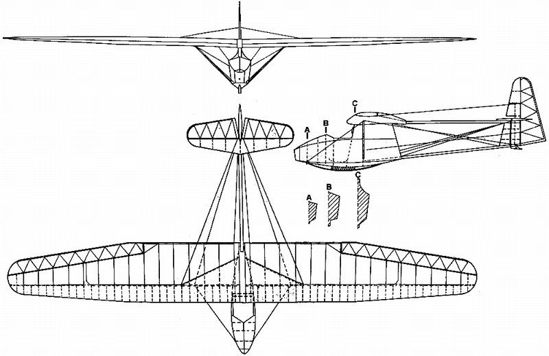
 Düzenleyen Nick_Karatzides - 29/01/2016 Saat 02:48 |
|
 |
|
|
Nick_Karatzides
Üye
Kayıt Tarihi: 06/06/2009 Aktif Durum: Aktif Değil Gönderilenler: 250 |
Gönderim Zamanı: 06/06/2013 Saat 22:49 |
|
Spartans refused to improve their long range weapons, because they always wanted to fight close to their opponent. That's why they had short length swords aka xiphos. Plutarch mentions in his "Lakonic Sayings" that when sometime an improved version of bow that could launch arrows farther to kill enemies from afar without risking presented to Spartan king Agesilaus, he replied: "Today the prowess died". This saying of the Spartan king Agesilaus came to my mind when I first heard about the 3D printers a few years ago and consider about the potential applications on scale modelling. For those who choose to deal with scratch building, the free access to 3D printer technology and the ability to create complete models or parts of a model using their home PC or laptop and CAD software rather building by hand, marks a new era in scale modelling. It is more than obvious that the time we spent to build from scratch using styrene sheet and X-Acto knife only, had ended and maybe in a few years there will be no more. It looks like "today, the scratch building died" On the other hand, we (as open minded scale modelers) could consider the 3D printing technology introduction into scale modelling and free access to the average modeller as an evolution in the hobby and a creative tool that helps us to build better and more realistic models. Certainly the new technologies and gadget tools in the hands of talented enthusiasts open new horizons and provide wide potentials on scale model building. If we had refused to take advantage of new tools, new incoming materials & resources offered by technology so far, we would never use airbrushes & air compressors for paint applying, we would never use pigments for weathering effects, we would never use new style micro tools & drilling devices, we would never use internet for know-how sources accessing and we would never exchange opinions through this forum. Having all the above in mind, I named the CAD & 3D printing as a new tool in my pocket (instead of cheating) from now on and Ill try to discover all possible alternative ways that could be used for best results. The modern scale modeller, except being a creative builder & talented painter, should also be familiar with other scientific fields such as:
...so, why not adding the CAD - Computer Aided Design & 3D printing skills? For those who might rush to say that this project is not a "scratch build", because the model did not actually "built by bare hands", I would answer as follows: Try to build your next model...
What Im trying here to say is that, just because it seems nearly impossible to imagine our hobby without the above stuff, just because the combination of "tools" plus "talent" plus "creativity" equals great building results, yes I believe that the 3D printing technology is actually in front of us and it will become a precious tool in hands of scale modeler. A new era is already here. Maybe, its about time for Spartan king Agesilaus, to reconsider his views.. |
|
|
|
|
|
Nick_Karatzides
Üye
Kayıt Tarihi: 06/06/2009 Aktif Durum: Aktif Değil Gönderilenler: 250 |
Gönderim Zamanı: 06/06/2013 Saat 22:56 |
|
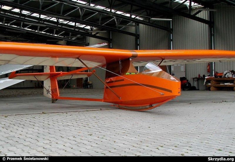
WWS is an abbreviation of "Wojskowe Warsztaty Szybowcowe" (meaning Military Gliding Workshops in Polish language), based in Krakow, Poland. Founded on 1935 by Waclaw Czerwinski who had taken over the management. The MRP-1 Salamandra project, was the first project which was created under his leadership. The Salamandra was a training glider, who had excellent flying characteristics, so that it was decided very quickly to take over in mass production in various workshops throughout Poland. Before the WWII, the Salamandra glider was also built under license in Yugoslavia and after 1943, the "Salamandra" was also produced in Romania. After the WWII, the production started again with a re-engineered version made from the IS which is an abbreviation of Instytucie Szybownictwa (meaning Gliding Institute in Polish language), under the name Warszawa IS-A Salamandra. During the 1950ies, the Salamandra glider has been built in China, where a two-seater version was also created. Around 500 Salamandra gliders have been built around the World, up to date. 
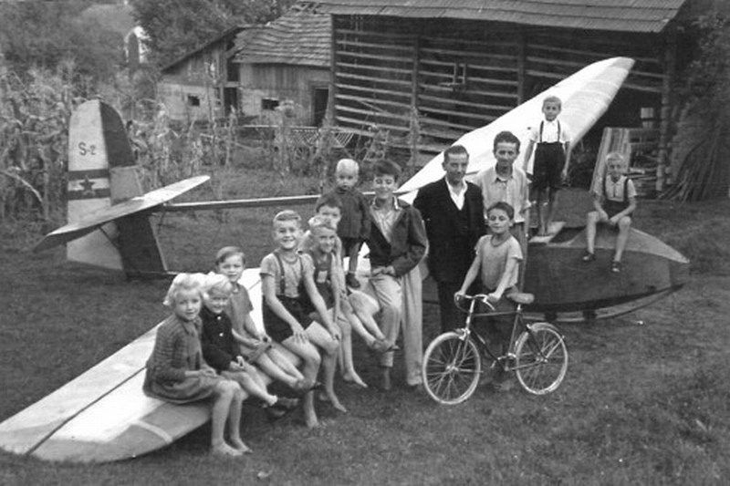
 The glider was also known by nickname "Czuwaj" among the Hungarian Boy Scout Association, which was the Polish version of the standard Boy Scout motto. 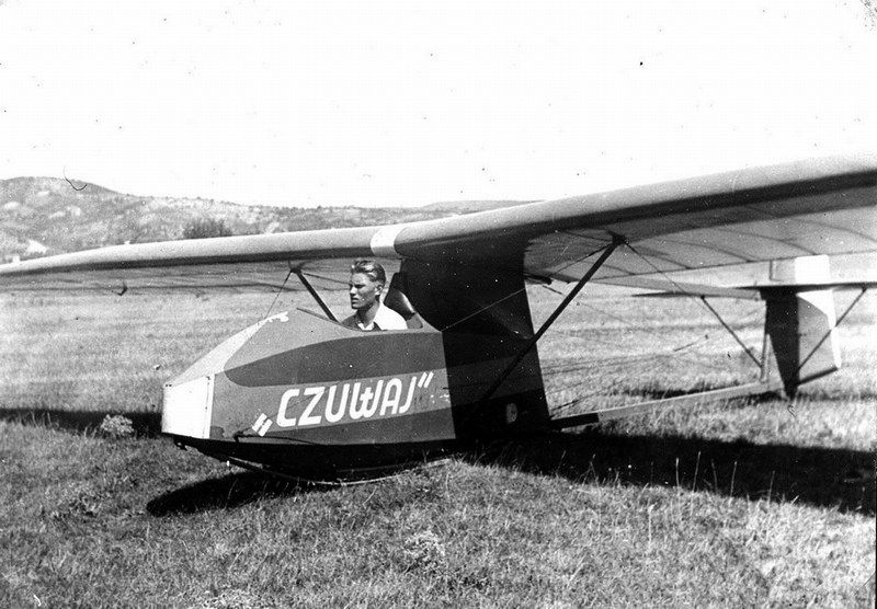 The WWS-1 Salamandra glider, also inspired the Finnish Pik-5 design. The Yugoslavian built version was developed by engineer Ivan otarić in 1939 and built by UTVA Panćevo factory as otarić UTVA Čavka. After the end of WWII, the Yugoslavian built Čavka model was widely used in Greece and became very popular among the glider aviators. Both Athens aeroclub based at Tatoi airfield and Edessa aeroclub based at Panagitsa airfield, used these gliders for young aviator training purposes. 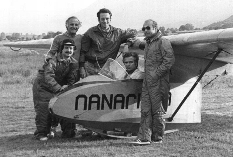
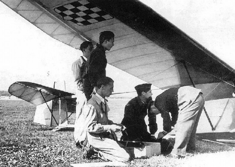
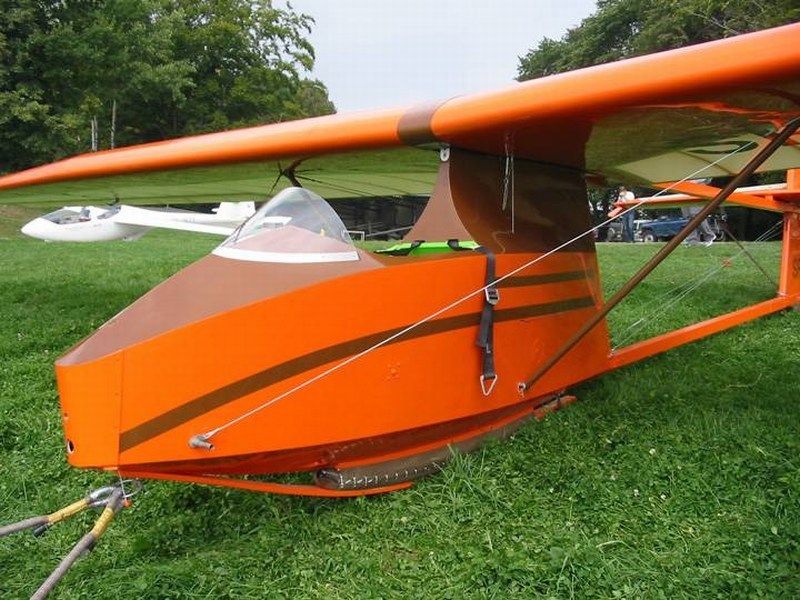
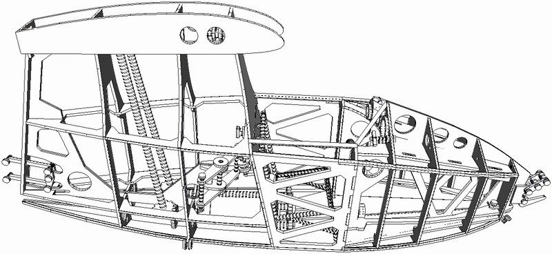
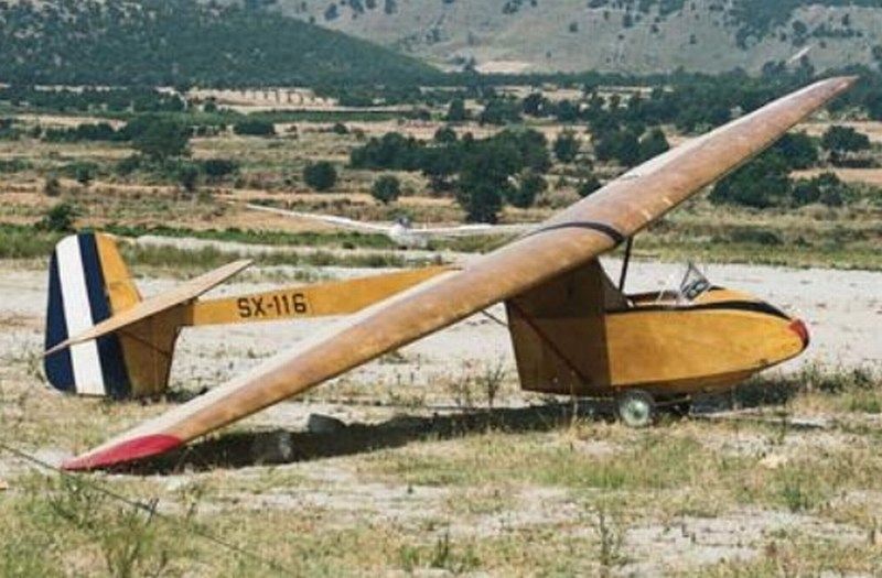 Construction of the Salamandra glider was entirely of wood with fabric covering on wings and tail unit. The fuselage consisted of a plywood covered nacelle for the single seat cockpit, with a wire-braced open strut rear fuselage supporting the cruciform style tail-unit. The high mounted wire braced wings were supported by struts from the bottom of the fuselage to approx 1/5 span. Later versions introduced windscreens and airbrakes in the wings. Wooden skids under the tail and fuselage nacelle comprised the undercariage. 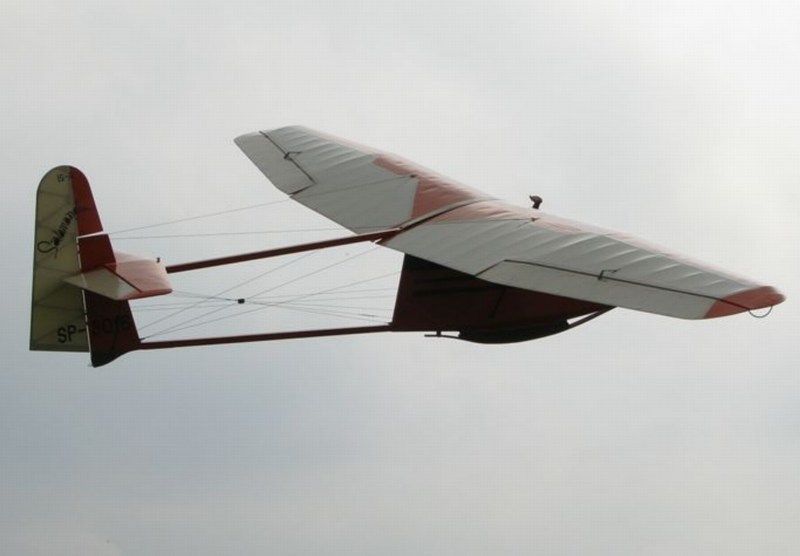
 Düzenleyen Nick_Karatzides - 29/01/2016 Saat 02:59 |
|
|
|
|
|
Nick_Karatzides
Üye
Kayıt Tarihi: 06/06/2009 Aktif Durum: Aktif Değil Gönderilenler: 250 |
Gönderim Zamanı: 06/06/2013 Saat 23:02 |
|
The technical data & general characteristics are:
[*]Usage: Solo training glider, [*]Crew: 1 pilot, [*]Year of first construction: 1935, [*]Country of production: Poland, Yugoslavia, Romania, China, [*]Length: 21 ft 3 in (6.48 m), [*]Height: 7 ft 6 in (2.30 m), [*]Wing span: 40 ft 11 in (12.48 m.), [*]Wing area: 16.9 m² (182 ft²), [*]Wing profile: Göttingen 378, [*]Aspect ratio: 9.2 / 1, [*]Empty weight: 309 lb (140 kg), [*]Gross weight: 496 lb (225 kg), [*]Maximum speed: 93 mph (150 km/h), [*]Stall speed: 24 mph (38.5 km/h), [*]Maximum glide ratio: 15.2 / 1 at 56 km/h (30 kts / 35 mph), [*]Rate of sink: 159.5 ft/min (0.81 m/s). 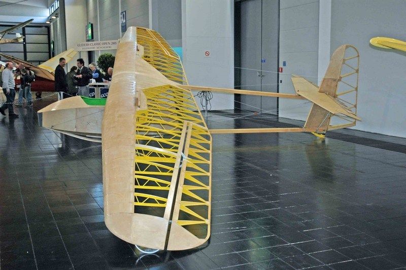 On 1967, Joseph Borzęcki converted a Salamandra to a motorized glider, equipped with a VolksWagen car engine 21 kW (28 hp) and named it "Cirrus". That specific motorized glider version, seemed very interesting to build under scale, but unfortunately I found out about it too late - I had already built the cabin and it was to risky to try convert the nose section in order house an engine. 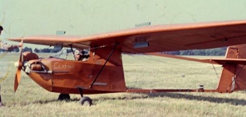 Most noticeable differences with the primary 1935 built WWS-1 model, are the presence of the retractable airbrakes on the upper side of wings and the squared tips of the elevator fins, as seen into following picture. 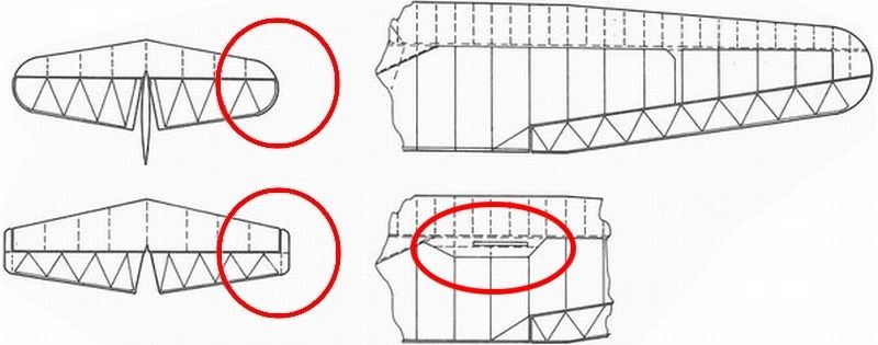 Düzenleyen Nick_Karatzides - 29/01/2016 Saat 03:05 |
|
|
|
|
|
Ares
Admin Group 

Kayıt Tarihi: 04/01/2005 Aktif Durum: Aktif Değil Gönderilenler: 3654 |
Gönderim Zamanı: 06/06/2013 Saat 23:05 |
|
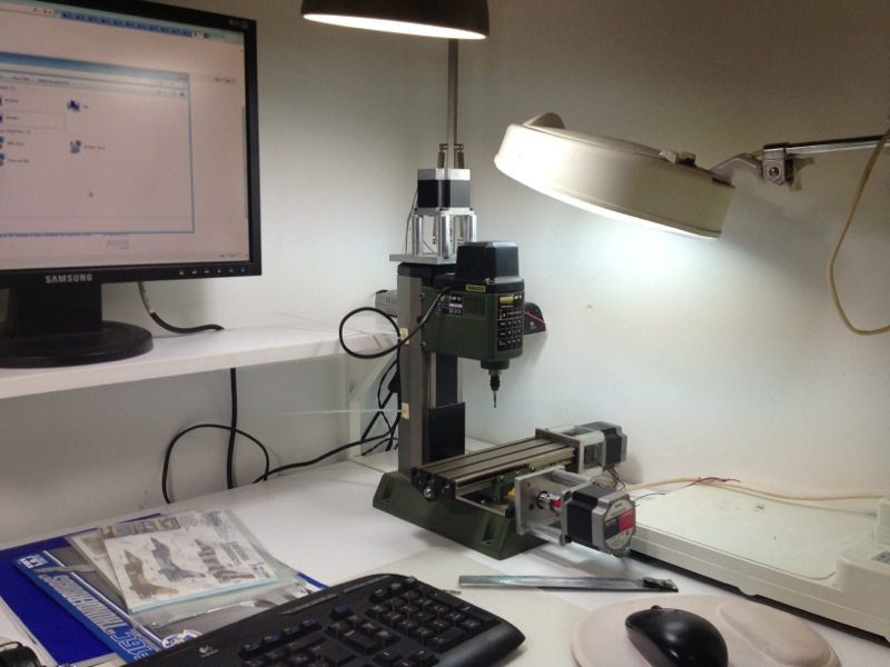
3D printing on IMHO for a better surface result, a CNC; a DIY solution of mine, I think it'll be operational next week.
|
|
|
Ares
If you're in a fair fight, you didn't plan it properly... |
|
|
|
|
|
Nick_Karatzides
Üye
Kayıt Tarihi: 06/06/2009 Aktif Durum: Aktif Değil Gönderilenler: 250 |
Gönderim Zamanı: 06/06/2013 Saat 23:07 |
|
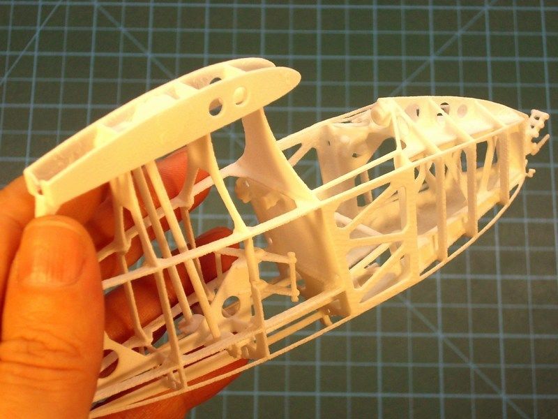
Before start building a new scale model, I always try to study as much as possible the object of construction. If books, technical manuals and detailed walkaround photos are available, that will help a lot the model building process. To know how it works and how exactly it is made on real aircraft, always helps to build the scale model. During the study that preceded this model construction, I noticed that the WWS-1 / IS-A glider is quite popular among the RC modelers, who use specific patterns to cut balsa wood and prepare their RC model parts. These patterns seem to be identical to the real glider construction frame, as found into a copy of the official technical manual, purchased from Krakow aviation museum. 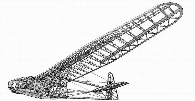
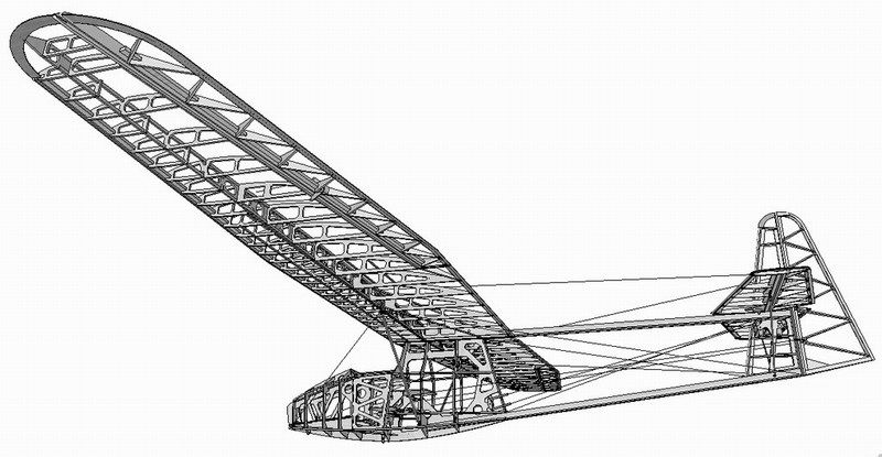
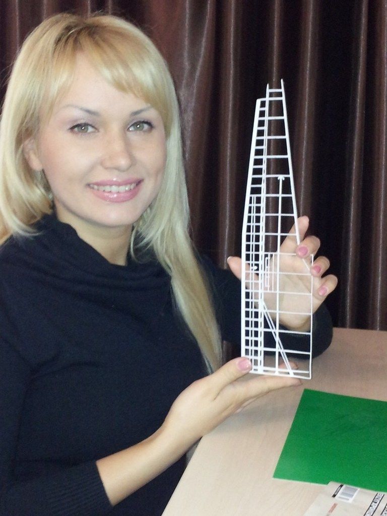
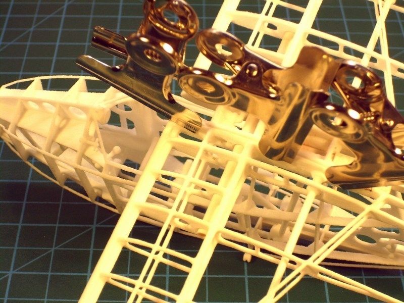
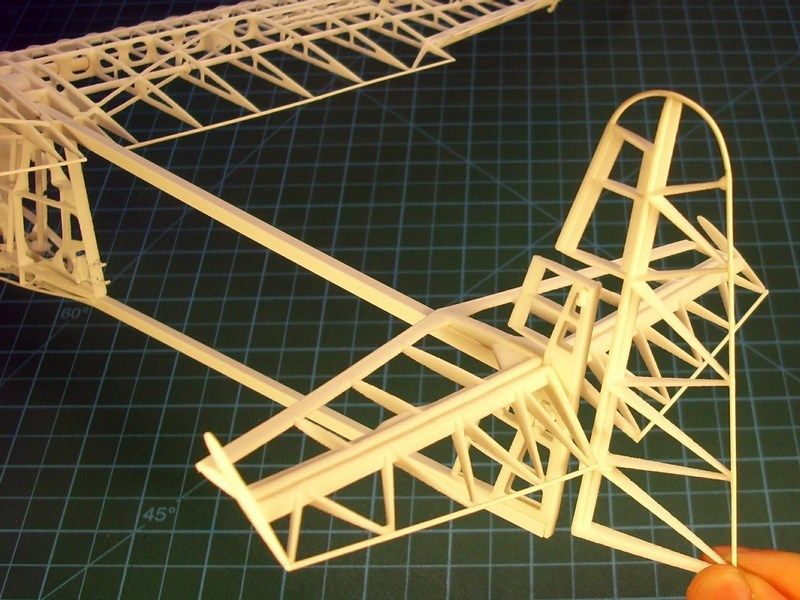
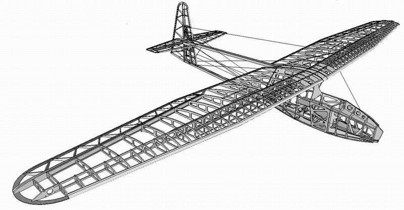 The building attempt, would not be successful without help from Mr. Ivo Mikač from Czech Republic, who kindly provided me with all info and the 3D plans he had previously create. Because these 3D plans were made for RC modeling purposes, I had to convert & detail them into something that could be much closer to my needs for static scale modeling. So, I spent few hours in front of my laptop, to scale down into correct 1/18 size and digitally cut (within a hundredth of a millimeter accuracy) the gliders compartments into virtual pieces, detail & improve the plans, having always in mind that the later printed parts, should perfectly fit and finally become a fine scale model. 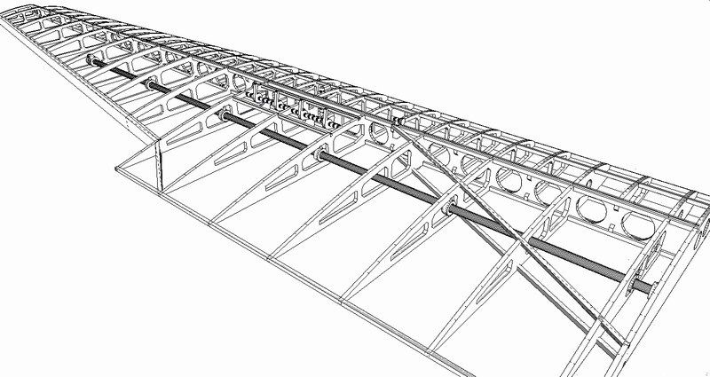 After converting the 3D plans as required and double check for possible mistakes, I saved it as a digital file and forward it on a 3D printer to start generating the individual parts of the model. Shortly thereafter, the printing proceeding outcome pleased me, while watching the Mbytes, magically converting into actual items. Yeah, thats what I call cool gadgets on scale modelers service. 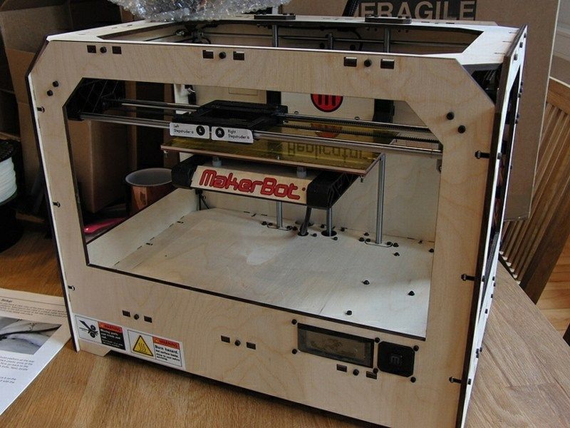 As seen in the following pictures, as soon as the produced parts were cleaned, I checked for broken parts & imperfections. The model now consists of only a few parts, found into three (cabin, wings & tail) basic frame sections. Some additional details such as wings supporting rods, control bars & wires etc made of styrene, will be later added.
[*]Left & right wings with separate left & right ailerons, [*]Elevator with separate left & right fins and stabilizer with separate rudder fin. 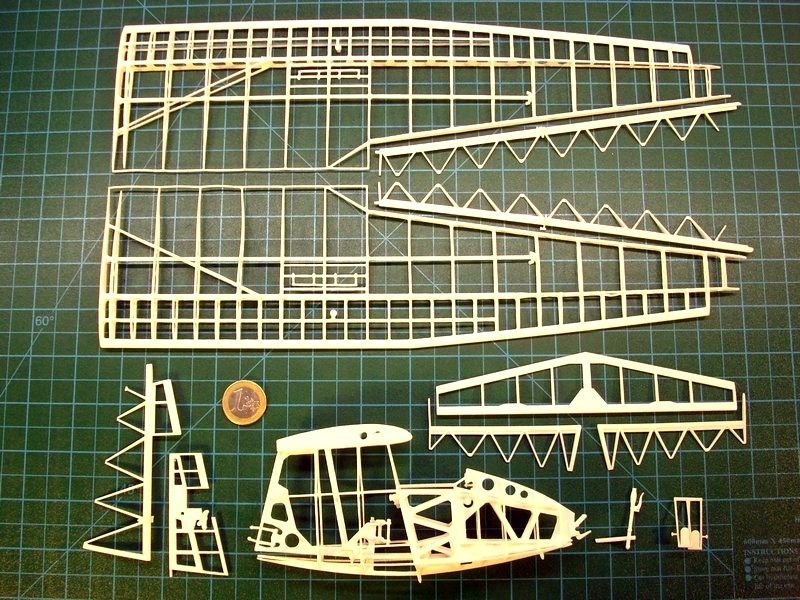
 After my sweetheart wife (aka 4-star General in home & family's financial director) conducted a strict quality control and 3D printing result evaluation, she smiled & proudly signaled green light for further building. After each section was dry fit tested to ensure that anything can be combined together as one piece, the parts forwarded for assembly. 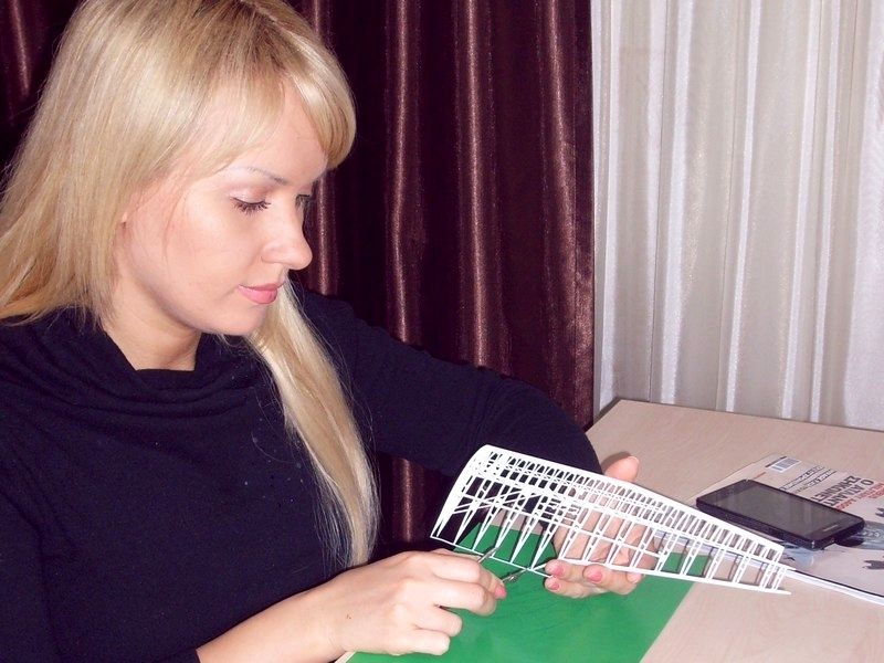
 Düzenleyen Nick_Karatzides - 29/01/2016 Saat 03:15 |
|
|
|
|
|
Nick_Karatzides
Üye
Kayıt Tarihi: 06/06/2009 Aktif Durum: Aktif Değil Gönderilenler: 250 |
Gönderim Zamanı: 07/06/2013 Saat 11:18 |
|
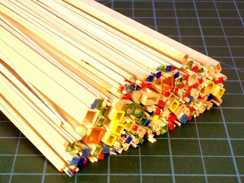
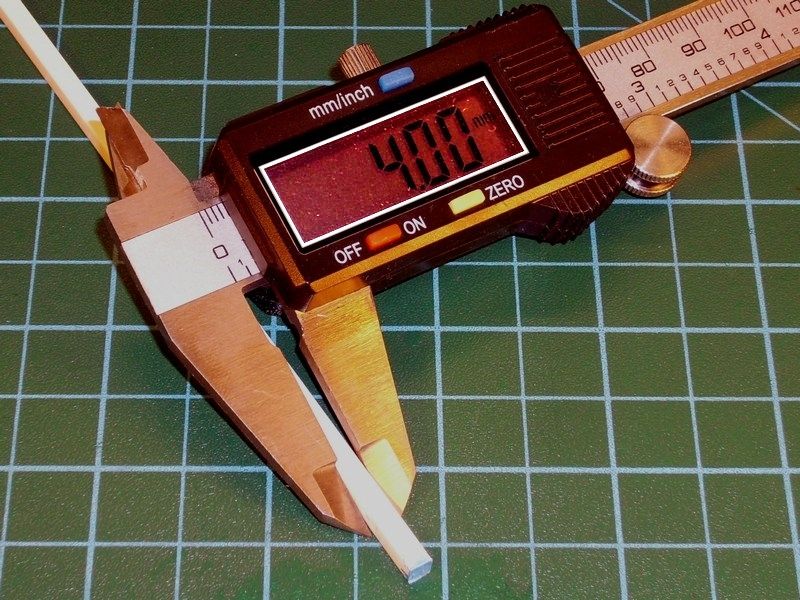
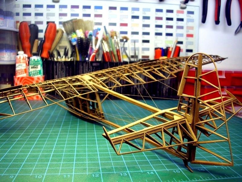
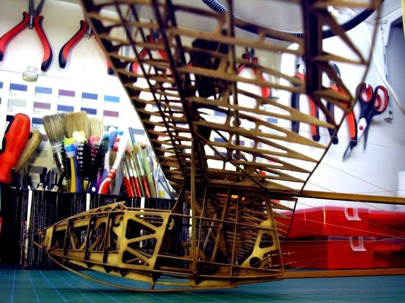
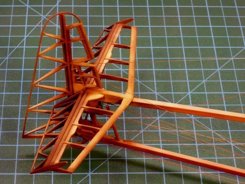
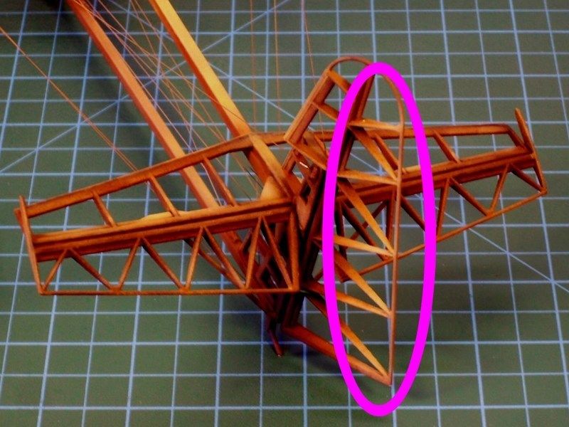
As soon as the individual scale models parts were already produced, cleaned & dry fit tested, I had to assemble everything as one piece, without damaging the frame construction. Just because the Salamandra was entirely constructed of wood, I decided that its much better to assemble all models parts first, sand if required and later apply paint and weathering effects as a final touch. During assembling process, everything was secured in place & glued with CA liquid adhesive superglue, which found at local market for 0.16 per tube (each 12-tubes card, costs 2 only). It does bonds in only few seconds, reaches extremely strength at room temperature and it is suitable for materials such as wood, rubber, plastic, metal, ceramics, leather, marble, polyethylene, polypropylene, teflon etc. Once I´ve tried this CA superglue on my scale models, Ive never go back. 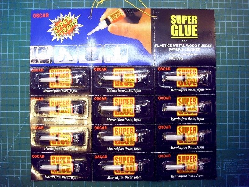 Following the 1/18 scale printed diagrams and using a new sharp Nr 11 stainless steel surgical blade and 4x4 mm sectioned styrene rod, it only took about 2 minutes to prepare the basic tail boom frame. The supporting frame consists of two 228 mm long beams that join the front compartment (cabin & wings), with rear part (tail elevator & stabilizer fins). 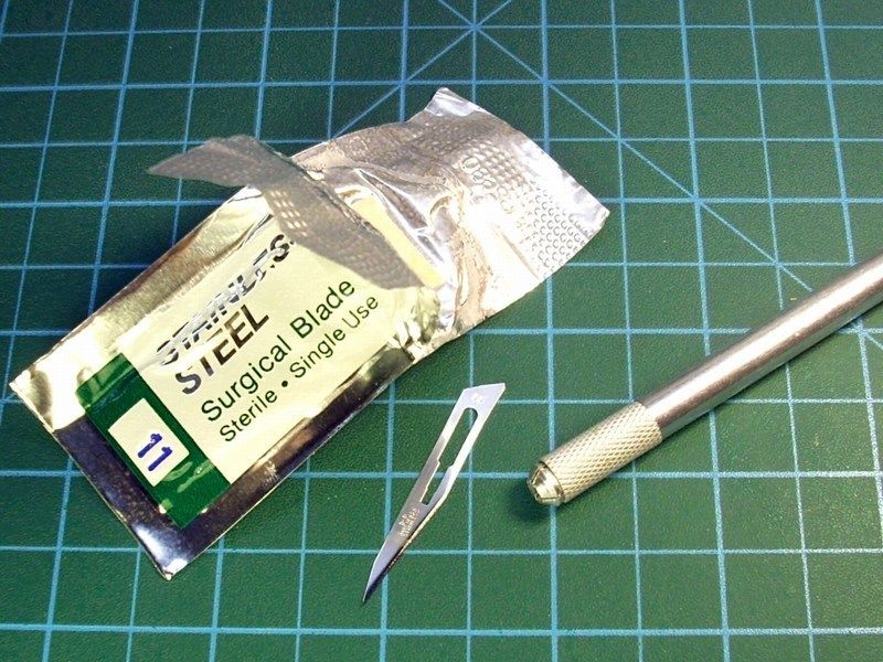
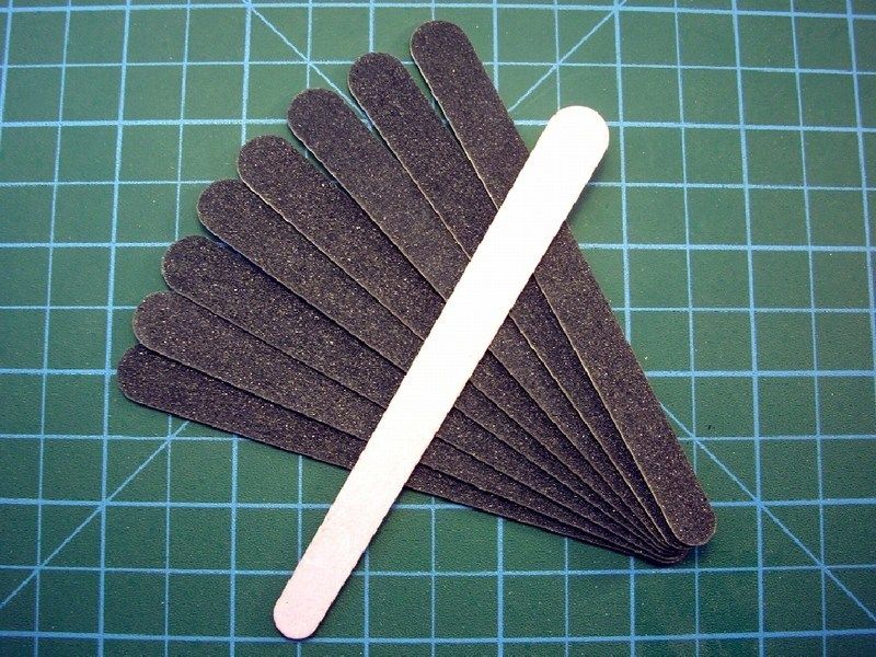
 The only piece that remained without gluing, is the tail rudder fin which will be set in place after paint. The glider models wingspan is now fully developed and looking really big as it is spreading lazily all over my working bench - approx 70 cm from one wingtip to the other. 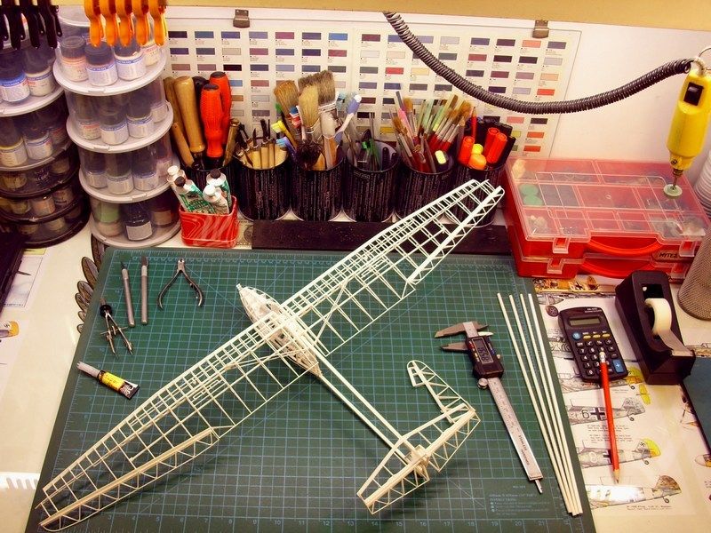 Some tiny gaps between the parts connections, were filled with putty, applied with an old brush. As soon as the joints between the cabin, wings & tail boom parts were securely glued with CA superglue and later filled with putty on tiny gaps, it was carefully sanded with nail files & sanding sponge block, found at the local beauty care shop - the only good moment when following wife on her shopping. They are cheaper than dirt, since each nail file cost 0.1 (each 10-nail files card, costs 1 only) and the sanding sponge cost 0.5 per block. 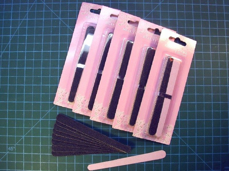
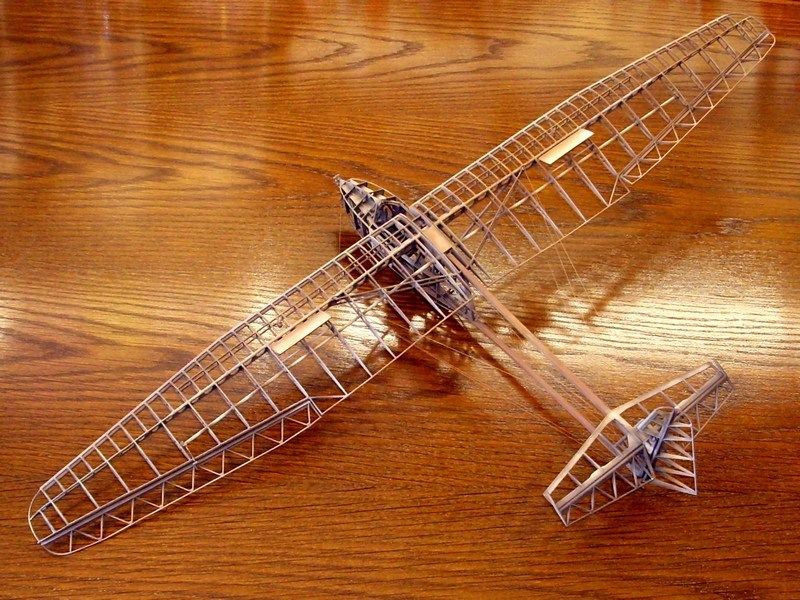
 When it looked OK to me, the whole model was sprayed over with Humbrol acrylic primer to spot any mistakes and placed into a box to wait the final paint applying. 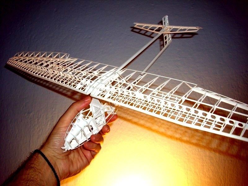 Düzenleyen Nick_Karatzides - 29/01/2016 Saat 03:20 |
|
|
|
|
|
Nick_Karatzides
Üye
Kayıt Tarihi: 06/06/2009 Aktif Durum: Aktif Değil Gönderilenler: 250 |
Gönderim Zamanı: 08/06/2013 Saat 19:49 |
|
As soon as the Humbrol light grey acrylic primer dried, the model washed with liquid soap and warm water to disappear leaving oil traces, fingertips etc. Usually, there are two available options for a scale modeler, to apply paint on a model:
[*]Assemble the scale model parts first and paint the overall built model later. While planing this 1/18 scale IS-A Salamandra model building, the 2nd option seemed as more appropriate and would make my job much easier. A really good reason to stick on this option, is the fact that the Salamadra glider's main frame was entirely constructed of wood. Ofcourse, fabric was covering the wings & tail and plywood was covering the cabins nacelle as well. But, since I had in mind to build this model as an artistic "cutaway" view, presented on its wooden frame only, I had no reason to avoid an overall wood colour tones painting. 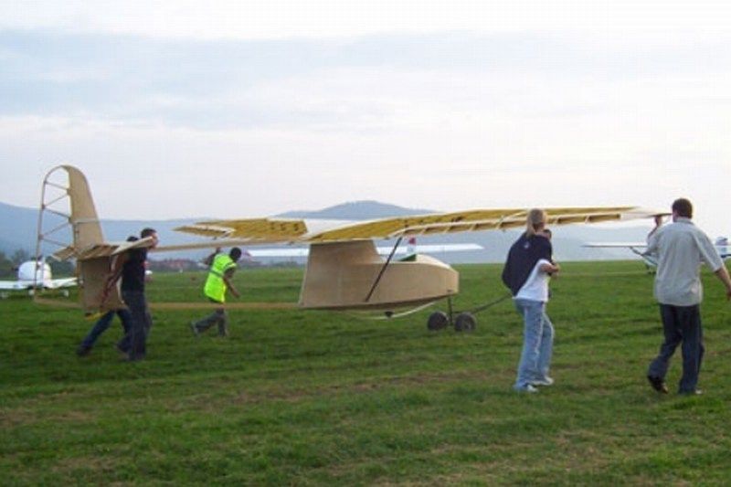 Replicating wood is one of those feared tasks in modeling that many try to avoid at all costs. Having a couple of different methods in mind to simulate wood in scale, but knowing that the following method is much accurate and easier to re-do if something goes wrong, I found good idea to follow some tricks I learned from other builders and changing things that works for me. To simulate the look of rough wood from which was made the glider's frame, I first applied a background colour. I split the areas to be painted in different categories and sprayed four different primary colors on each area. I used the following colors, which seemed to work OK for me, for the basic background. It is important to use an acrylic base colour because it is chemically impervious to the steps that follow.
[*]FS30400 "German Desert Yellow" available by Life Color as UA084 acrylic, [*]FS30257 "Sand Yellow RLM79VAR" available by Life Color as UA081 acrylic and [*]FS30140 "US Brown Marrone" available by Life Color as UA085 acrylic. 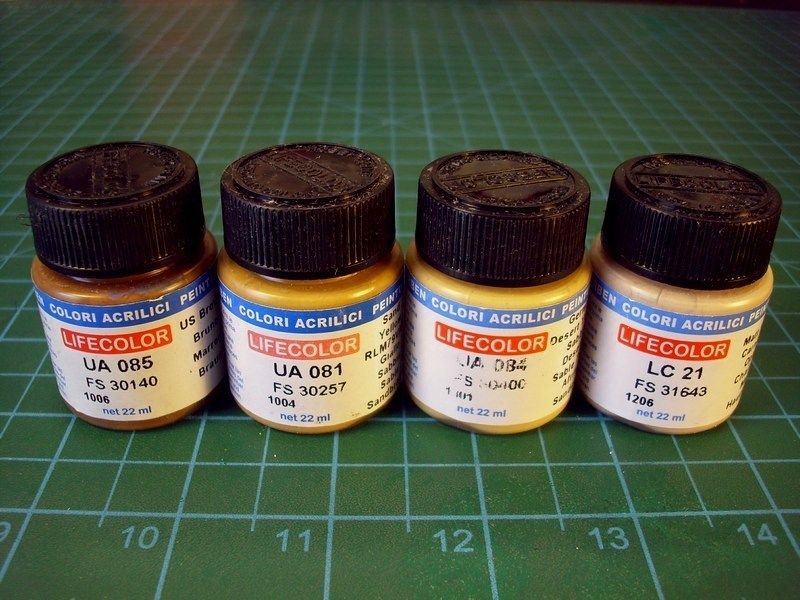 Because the wood composition and quality was not the same everywhere, I also use the Life Color's "Weathered Wood" 6-pack set and repeatedly covered some areas with different shades of very very very diluted & light layers over the previously applied base colours. To do so, I used the following:
[*]Life Color UA718 "Wood Cold light shade" acrylic, [*]Life Color UA715 "Wood Warm light shade" acrylic, [*]Life Color UA716 "Wood Warm light shade 2" acrylic, [*]Life Color UA714 "Wood Warm light base" acrylic and [*]Life Color UA713 "Wood Warm dark shade" acrylic. 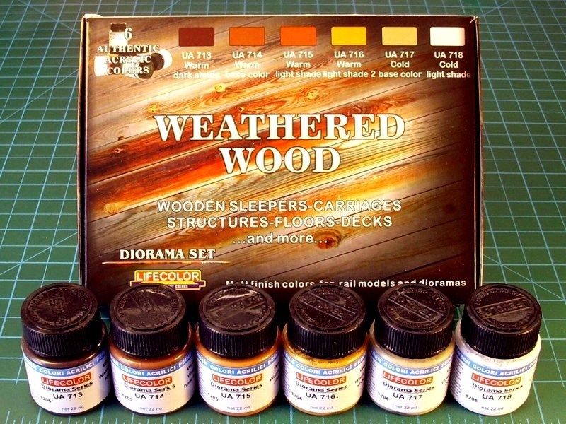 I'm not really sure if it is actually vissible into following pictures, but repeatedly applied very diluted & light layers, resulted more natural look of wood shades, without even aplly any oil colours yet. The first applied base colours, are visible under the later applied layers of the "Weathered Wood" shades, setting a base for the next process. 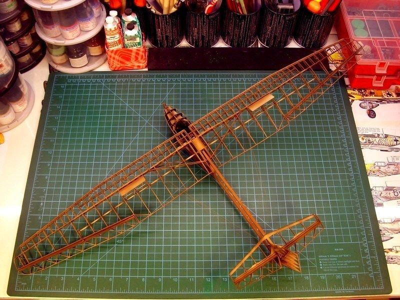
 Düzenleyen Nick_Karatzides - 29/01/2016 Saat 03:28 |
|
|
|
|
|
kaancolak
Yeni Üye 

Kayıt Tarihi: 02/06/2013 Konum: Turkey Aktif Durum: Aktif Değil Gönderilenler: 1 |
Gönderim Zamanı: 09/06/2013 Saat 23:05 |
|
That's what I call scratch building of a model kit. Following up!
|
|
|
Who is John Galt
|
|
|
|
|
|
Nick_Karatzides
Üye
Kayıt Tarihi: 06/06/2009 Aktif Durum: Aktif Değil Gönderilenler: 250 |
Gönderim Zamanı: 10/06/2013 Saat 01:24 |
|
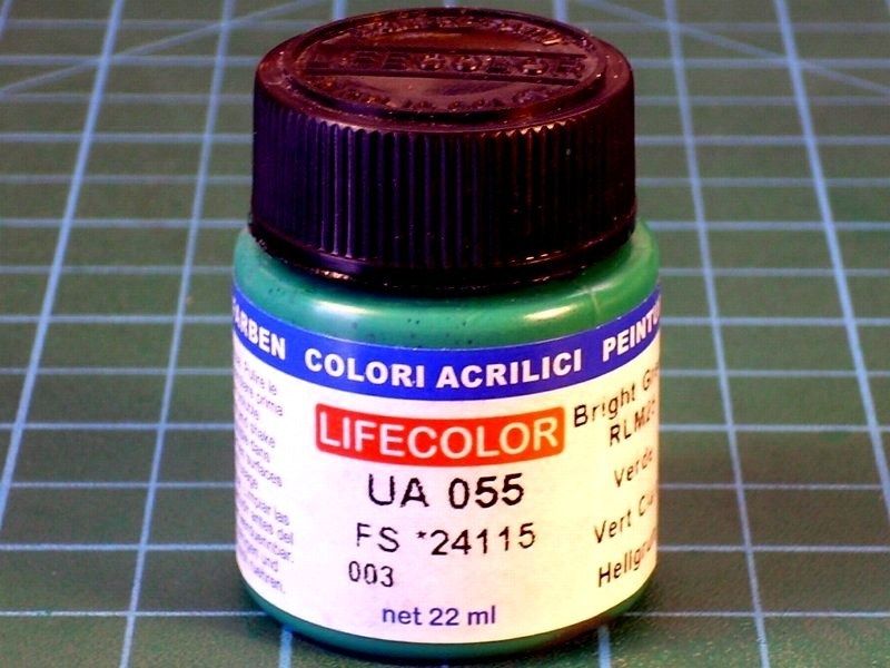
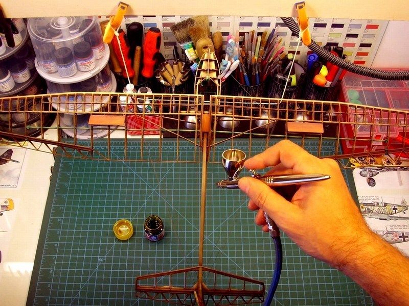
Studying the available photos I have, whether from my visit to the Polish aviation museum Krakow, Poland or pictures came from individuals who have built IS-A replicas around the World, I noticed that some of the metal parts ie control surfaces rods and cockpit levers, are painted with a green colour, which looks much alike the green that Soviets used to paint their jet fighter cockpits. To be honest, since all the 60 - 70 years old pictures are B&W, I'm not really sure if the actual IS-A gliders had these parts painted green, or if its just a practice by modern replica manufacturers. I decided for artistic reasons only and without being able check this feature authenticity, to paint these levers & rods with mentioned green colour. To do so, I used the FS24115 "Bright Green RLM" available by Life Color as UA055 acrylic and later blend it, to look brighter on middle areas, spraying much diluted FS30257 "Sand Yellow RLM79VAR" available by Life Color as UA081 acrylic, just not to look too dull.
 After the green parts painting & lighting, I repeatedly sprayed a very diluted mixture of thinner, Life Color UA717 "Wood Cold light base" acrylic and Life Color UA716 "Wood Warm light shade 2" acrylic at a ratio of 90% - 5% - 5%, over selected areas such as the wings leading edges and a few other points, that should look more enlightened. 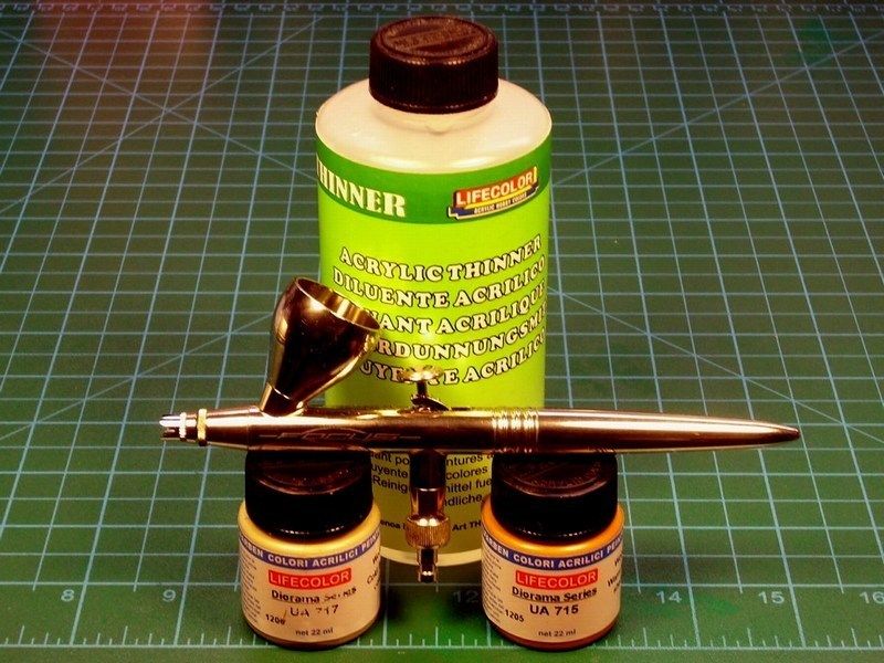
[*]THE BAD NEWS: I did the stupidity to use the cheap matterial, in order to keep low the printing cost. And yes, these 3D printer traces, which before painting did not even appear, are now slightly visible. [*]THE GOOD NEWS: These printer traces, (am I lucky or not?) look like wood grains! Yeap, that suits me a lot, because what I 'm trying to simulate here, is a glider frame made of unpainted, rough & hard wood. Since other scale modelers try to replicate this exact wood texture effect, I've already have it 3D printed in front of me. 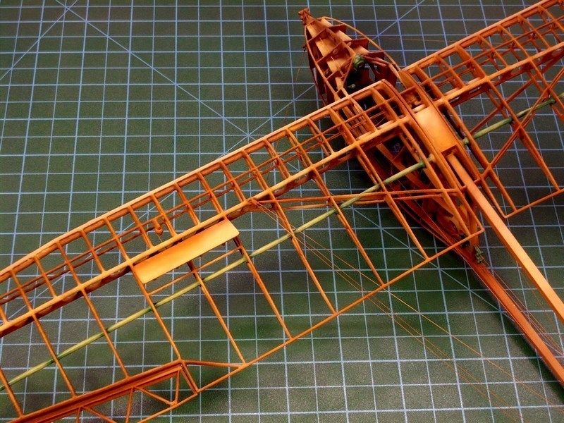
 Düzenleyen Nick_Karatzides - 29/01/2016 Saat 03:43 |
|
|
|
|
|
Blackbird
Üye
Kayıt Tarihi: 17/09/2006 Aktif Durum: Aktif Değil Gönderilenler: 660 |
Gönderim Zamanı: 10/06/2013 Saat 23:25 |
|
So glad that the bad news has turned into a good one. Stunning work.
|
|
|
|
|
|
Nick_Karatzides
Üye
Kayıt Tarihi: 06/06/2009 Aktif Durum: Aktif Değil Gönderilenler: 250 |
Gönderim Zamanı: 15/06/2013 Saat 22:02 |
|
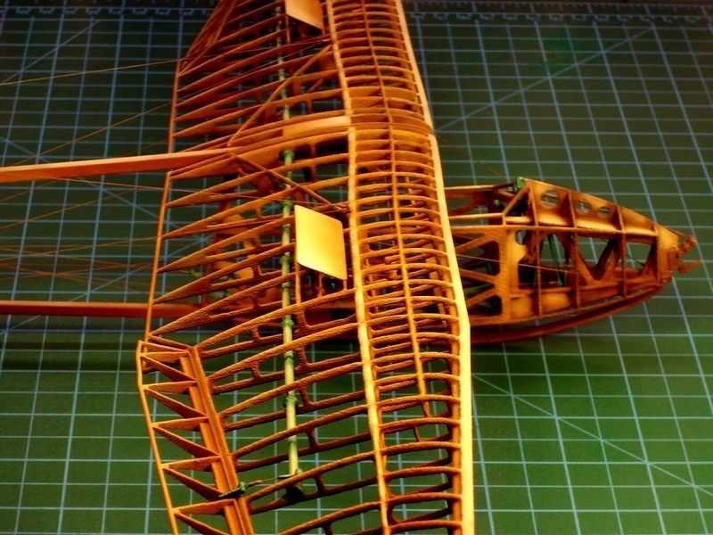
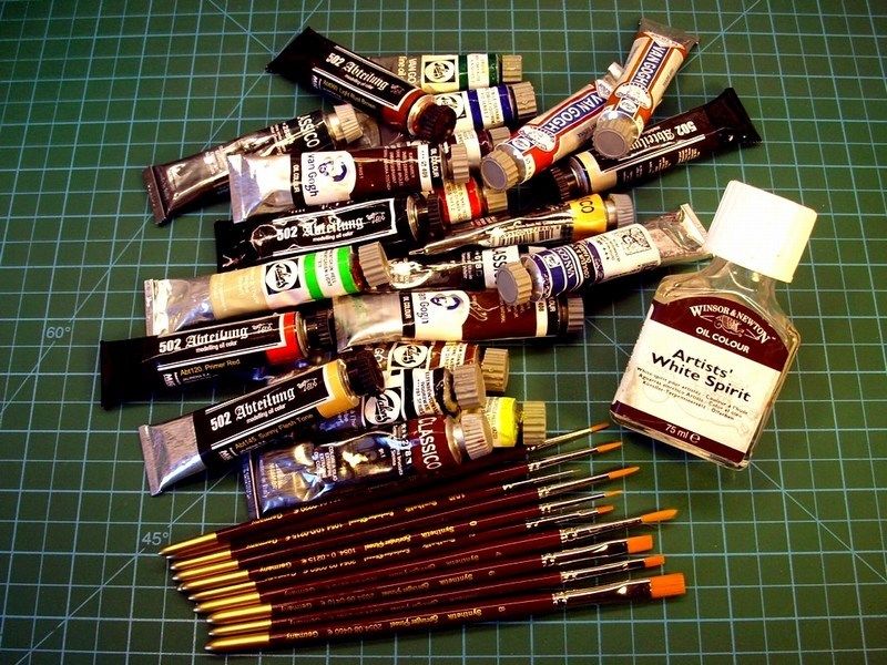
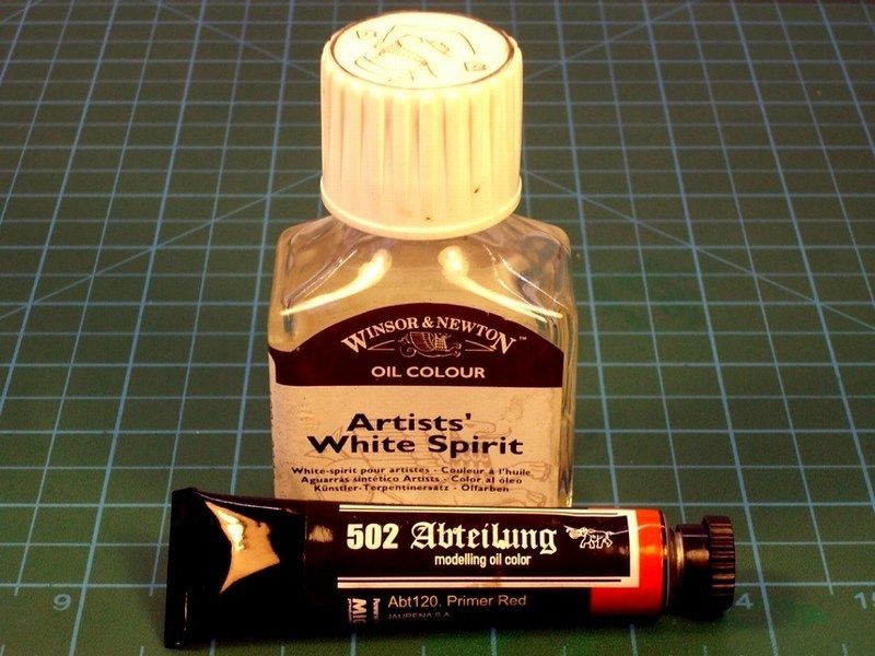
To apply the wood grain on wide areas covered with plywood, such as the airbrakes, I used wood grain colour from artists oil paints. The higher quality artists grade paints work much better because the pigments are much more finely ground. I believe that 502 Abteilung by MIG Productions, Van Gogh and Talens are good brands. The colour of the background coat and the oils may be varied for different kinds of wood. However, be aware that selecting a good colour combination that gives that natural look is tricky. I recommend experimenting on a test piece first before committing yourself to apply the mixture on your latest wondermodel. I arrived at my blend of "Burnt Sienna", "Yellow Ochre" and "Raw Umber" in a ratio of 25% / 25% / 50% after trying with "Raw Sienna" (too red), "Yellow Ochre" (too orange), and one or two mixed combinations.
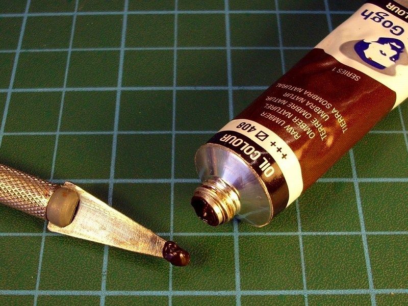
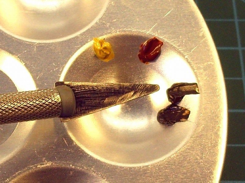 Once the base coat has cured, I brushed the oils with a broad, soft brush and spread the paint around until the desired colour density is achieved. Because working in oils is a little bit goes a long way, I started by putting just a little bit of paint on the end of the brush. I kept the brush strokes going in one direction and didnt really worry about leaving brush strokes - I wanted them there for the wood grain. I tried not to spread it on too thick, or it would make the next step more difficult. 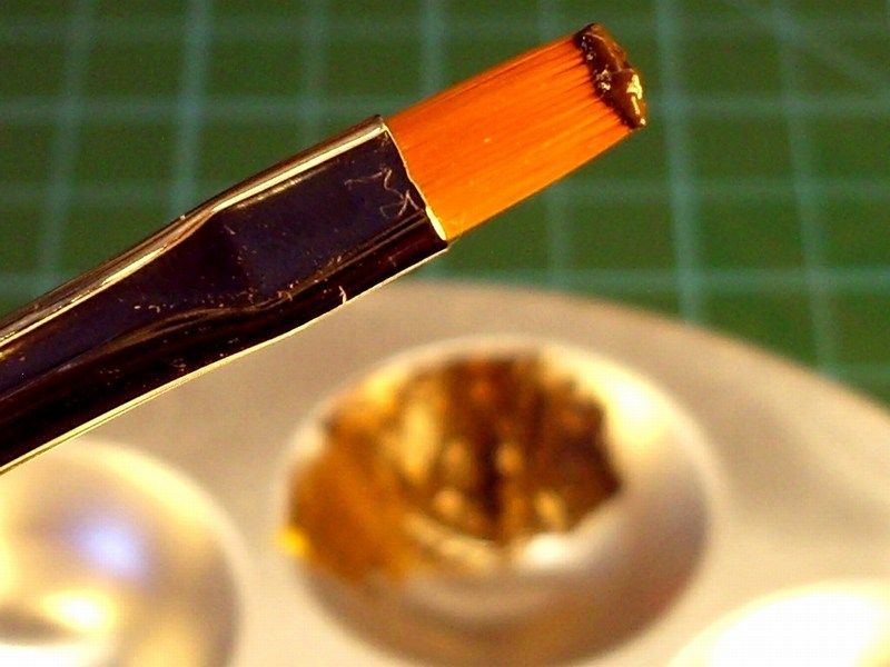 At this point the oils would be workable for several hours. With a broad, soft, clean and completely dry paint brush, I draged over the oil paint, leaving wood grain streaks. I jiggled the brush every now and then to give the grain a bit of variation. As the brush picked up the paint, I wiped it off on a clean, lint free cloth and continue process. Lint free is the key phrase, as any speck of lint would adhere to the oil paint and destroy the finish. The beauty of this technique is that you can clean the oils off and try again if you goof up. Use a clean cloth and paint thinner (mineral spirits or turpenoid - not lacquer thinner) to wipe clean any mistakes and start over again. For my 1/18 scale Salamandra model, it took me about three or four tries to get the paint density and colour right, but it really was quite painless. 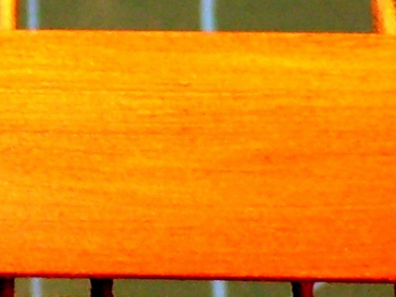 In some parts of the model which should look more bright, I slightly toned up with "Buff" & "Yellow Ochre" mixtures, or even pure Basic Flesh Tone" and Sunny Flesh Tone", while some others had to show darker, using "Brown" or "Raw Umber" color and blend naturally. The areas marked with yellow circles supposed to be covered by plywood and the areas marked with purple circles supposed to be more bright and slightly toned up. 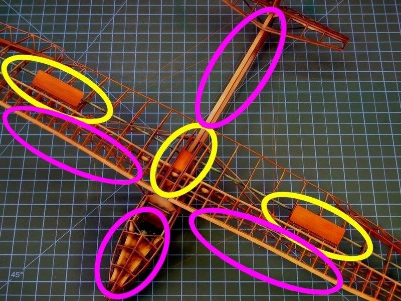
 As soon as the result was OK for me, I left it alone to dry for few days and then sprayed over selected areas with Tamiya Color X-24 "Clear Yellow" acrylic, because it also helps bring the grain color out more. 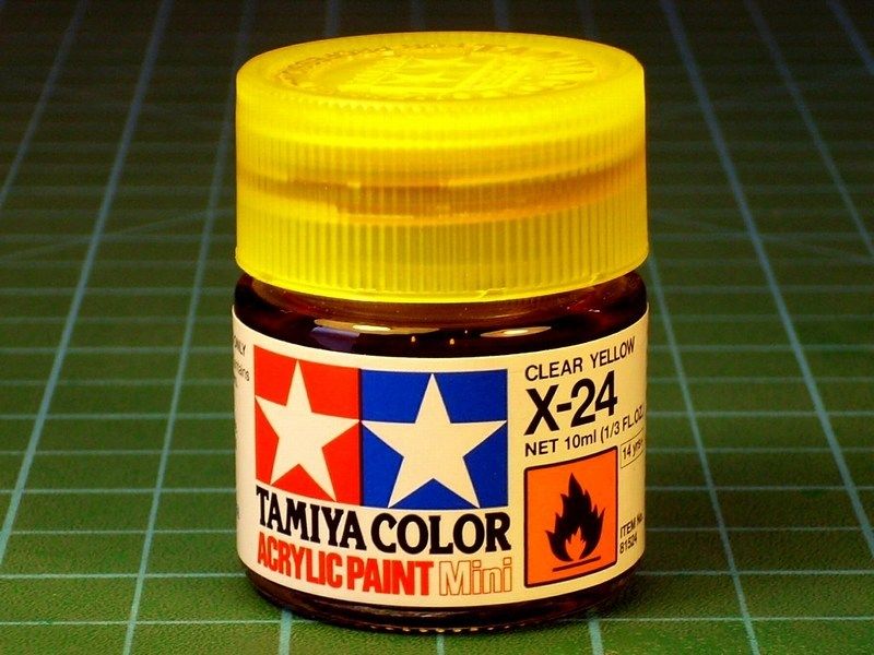
 Düzenleyen Nick_Karatzides - 29/01/2016 Saat 03:54 |
|
|
|
|
|
Nick_Karatzides
Üye
Kayıt Tarihi: 06/06/2009 Aktif Durum: Aktif Değil Gönderilenler: 250 |
Gönderim Zamanı: 04/07/2013 Saat 05:35 |
|
When I started this project, I was concerned about the proper display option, on which the model would be placed. For this reason, I asked fellow modelers to advice on how they would do if in my position. Talented & world class scale modelers such as Mr. Rick Lawler from AK interactive team, honored me by sending their kind answers, suggesting what best to do according their opinion - I thank them all. Most of the responses I got, recommended simplicity & austerity with no extra diorama features. Just to place the cutaway shaped model onto a dark colour or black) shiny laminated wooden base, so that nothing would distract viewers attention from main subject - the Salamandra cutaway. Following their advice, I tried some dry fit tests with few spare laminated wooden bases I had, to check how it looked like. I tried different shades of wood and finaly black sheet of plexiglass. Evidently the visual experiment clearly proved that the model got nearly disappeared into the natural wooden base's background, regardless of whether the background was light, medium or dark wood. Since the actual IS-A frame was entirely made of wood, it seemed that placing the model on a wooden base, might not be good idea. Black plexiglass tests, also didnt looked right to me. 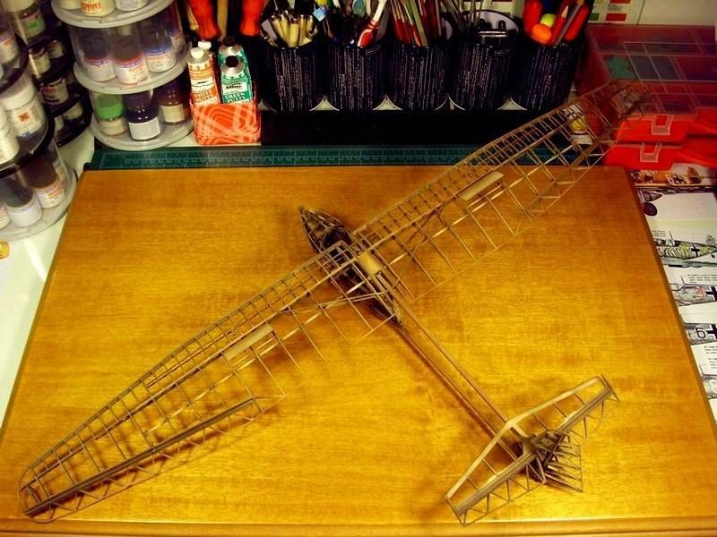
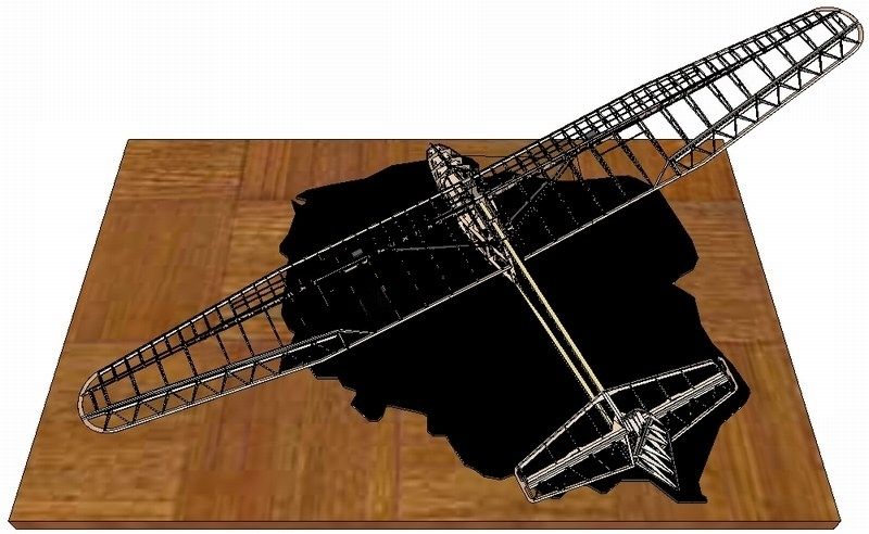
 I also received suggestions for mounting the glider on a clear pole which seemed nice idea, but models cutaway stucture was too fragile to be securely pinned on a single point. I also tried to digitaly create a virtual model, with the glider placed on a concrete tarmac or shiny black ground, cut on Polands map shape - since the IS-A was a typical sample of pre WWII Polish aviation design. 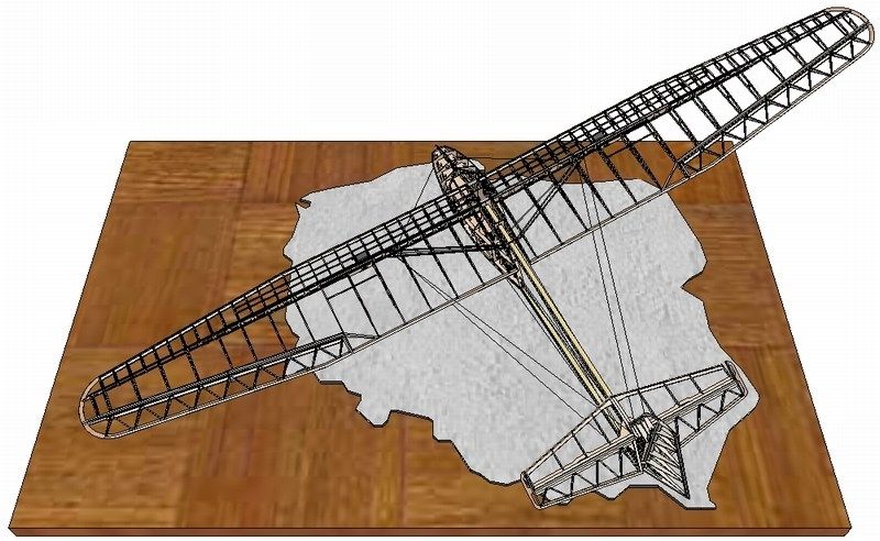
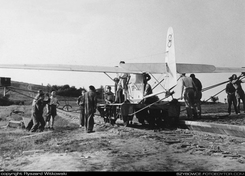
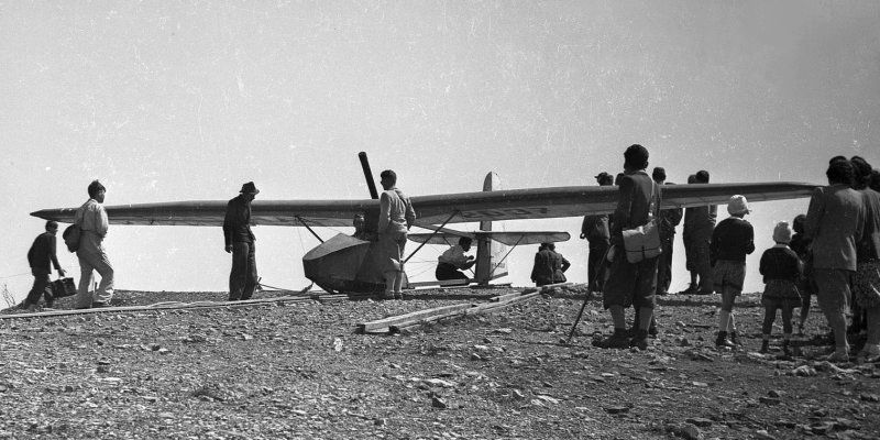
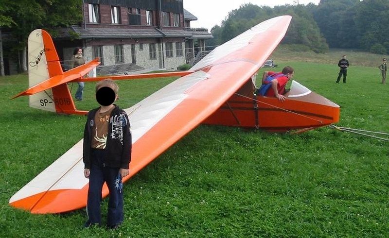
 I was almost sure I was going through a non-creative phase and getting ready to pack the model in a box and store it until having some good idea. Unexpectedly, I became obsessed with the idea of placing the glider model on a "grass airfield" dio base. Probably, my opinion had been shaped (aka influenced) by viewing the following two pictures, where the IS-A glider is laying on the Spring green grass. 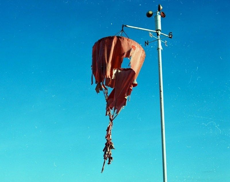
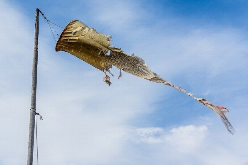 My goal is to recreate a scene of an aeroclub small airfield, where the old Salamandra is now resting in peace. I ll try to place the glider in such a way that will look like an old time abandoned wreck, with all plywood & fabric lining removed, tilted sideways to rest on the short green grass field, with one wingtip touching the ground and the other on air. Some torn fabric & plywood parts would be also laid nearby, some rusted & cut wires, possibly a couple of Marsden matting / PSP - Pierced Steel Planking plates or maybe a waving windsock etc. could be also present in scene. In general, a picture of terse abandonment, without extreme features that could distract viewers attention, keeping the glider as the main protagonist of the story. From an artistic point of view, the abandonment might possibly dictate everything to be into a state of complete wreckage. That would not be the desired result, because it would lead into a diorama scene, where the Salamandra would no longer be the protagonist. My aim is to balance the scene, while filling empty space & keeping the IS-A as the only "model" on display. 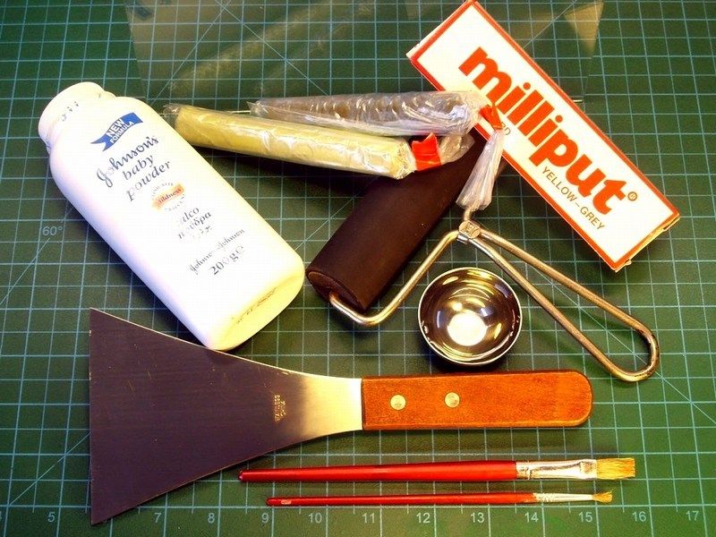
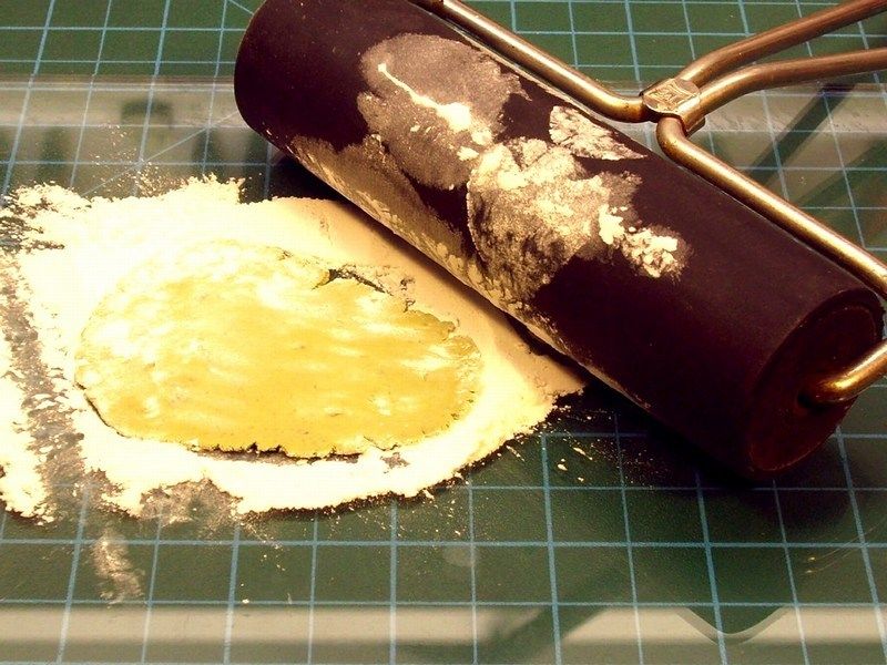
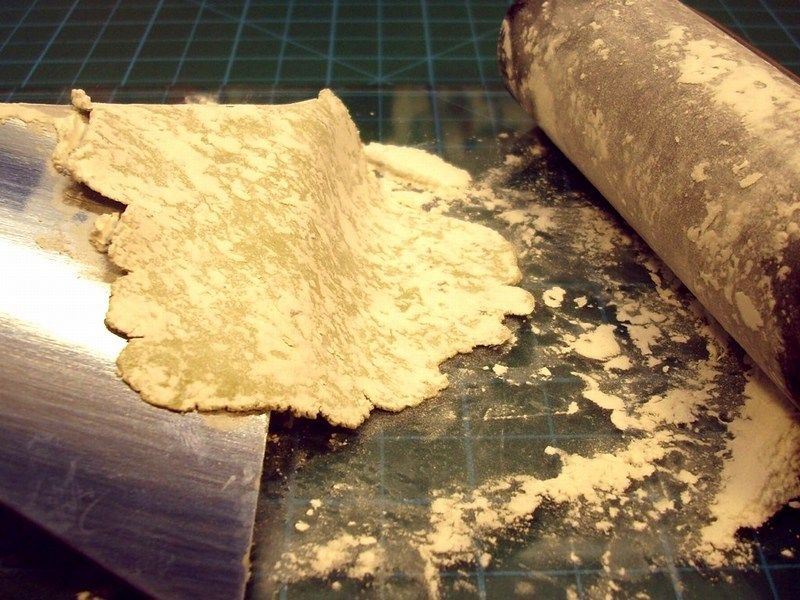
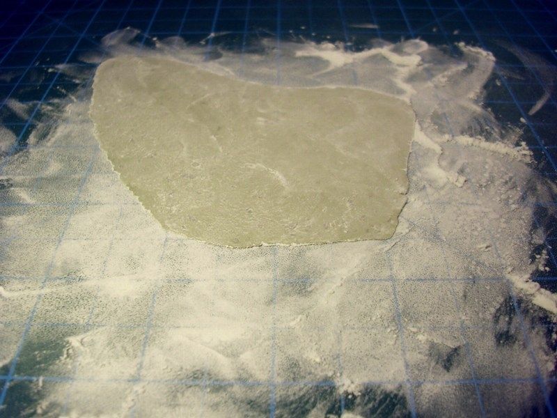
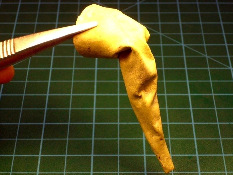
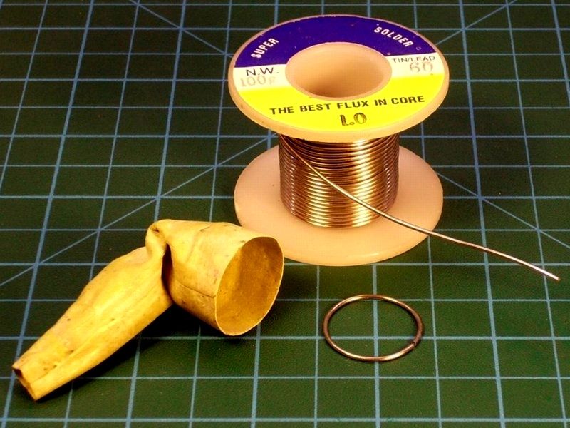
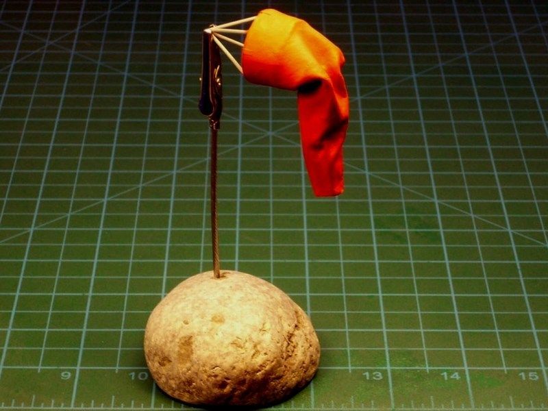
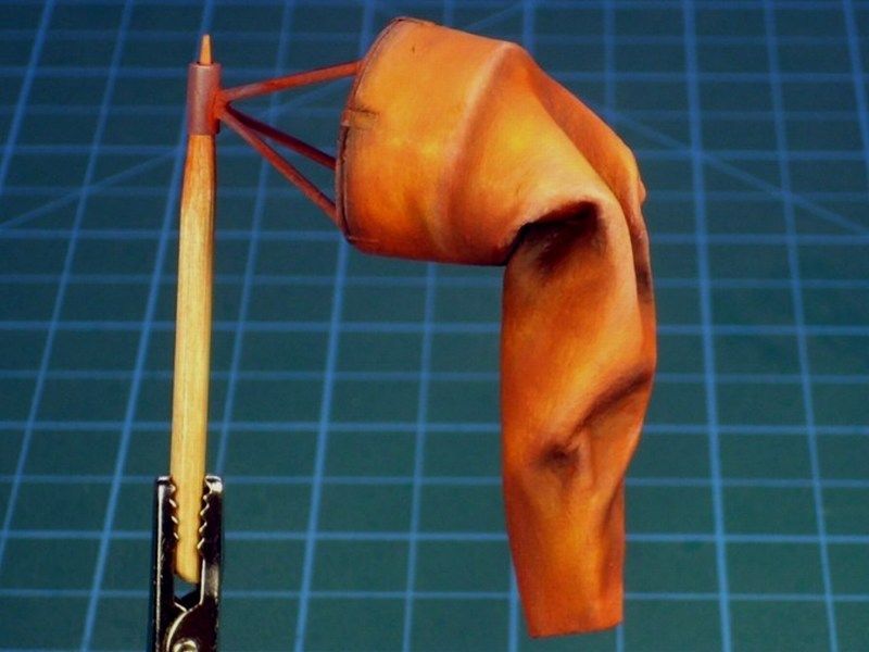
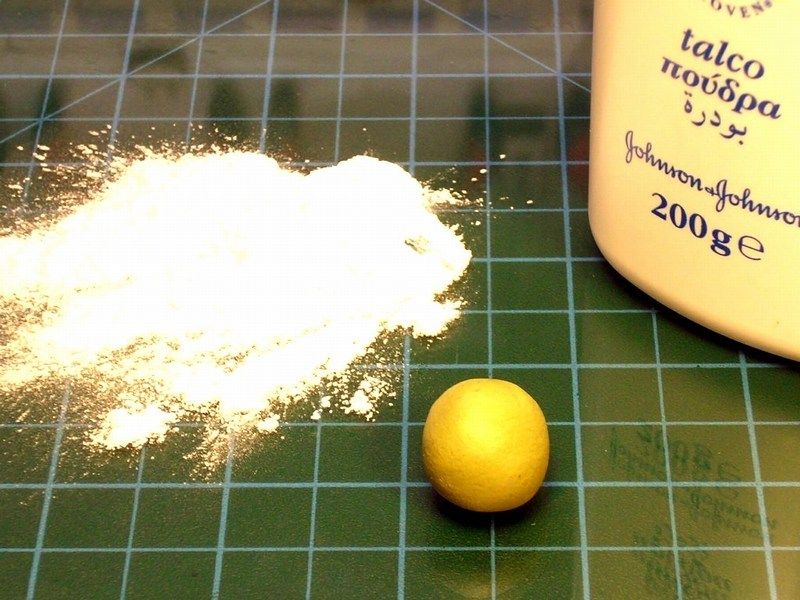 I found the idea of a deflated windsock nice, in order to fill some empty space and break the monotony of green, while remaining in scene's background same time. Although a picture of a torn windsock would be more atractive & interesting, I had to keep it simple and not overdo. Using a small amount of Milliput putty, I made a small ball, dust it with talcum powder and pressed it against the working bench with a roller until it becomes as thin as could get. The use of talcum powder is necessary to avoid Milliput sticking on roller or fingers and get easier to handle without tearing to pieces. 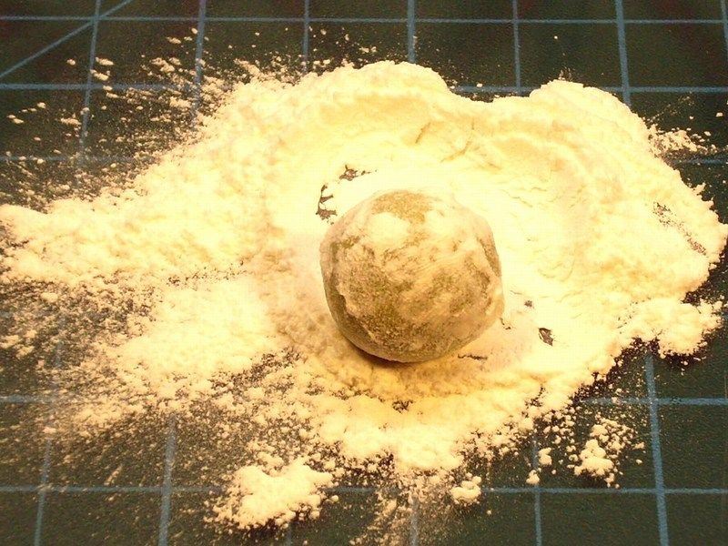
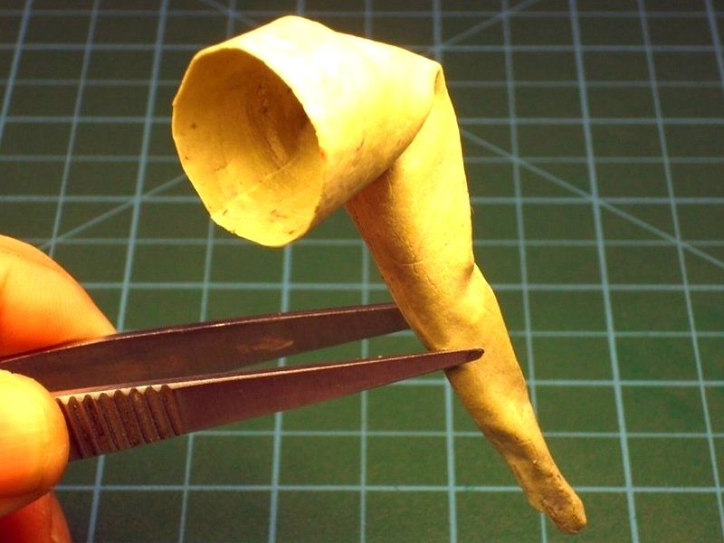
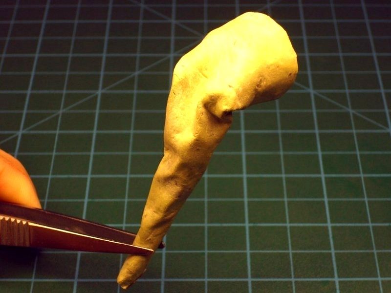
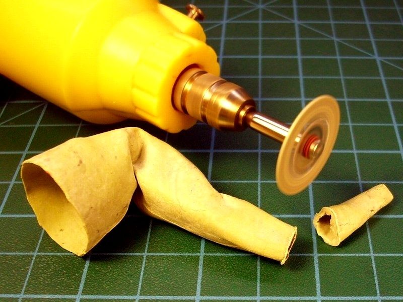
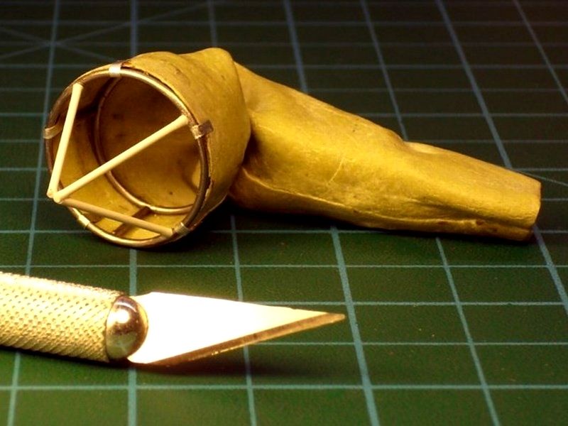
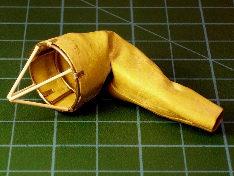
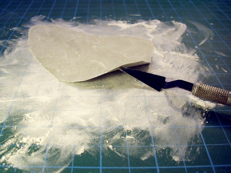 While Milliput putty was still soft, I cut it into triangle shape and rolled it up, to form into a right to scale windsock cone. Then, the cone was bended as required to look deflated and simulate cloths weight. The result made of epoxy putty (seems like elephant's proboscis or its just my imagination?), left few hours to get fully polymerized and then I cut the tip to achive the correct lenght dimensions. Few epoxy overcast remains that were left, also removed during cutting process. Internal frame added later, using metal wire & styrene rod. 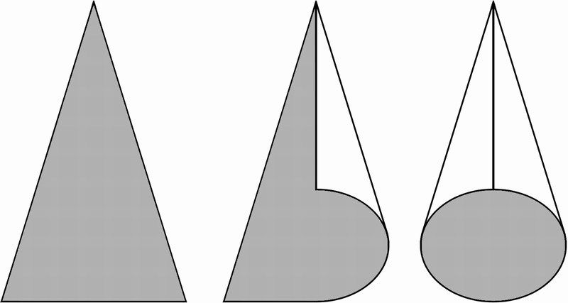
 Düzenleyen Nick_Karatzides - 29/01/2016 Saat 04:07 |
|
|
|
|
|
Nick_Karatzides
Üye
Kayıt Tarihi: 06/06/2009 Aktif Durum: Aktif Değil Gönderilenler: 250 |
Gönderim Zamanı: 05/07/2013 Saat 22:57 |
|
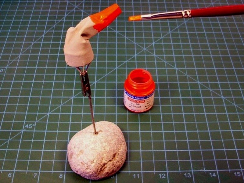
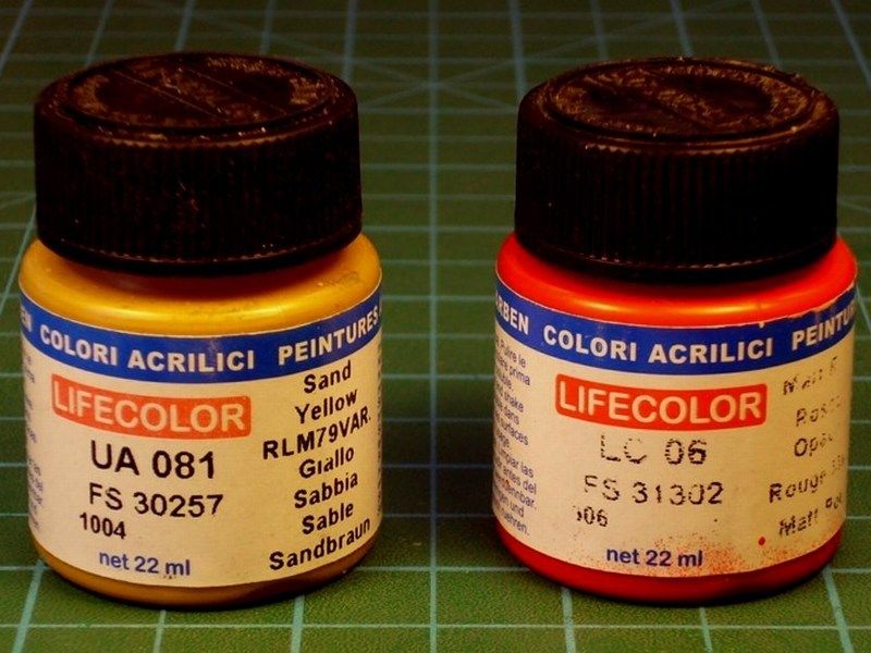
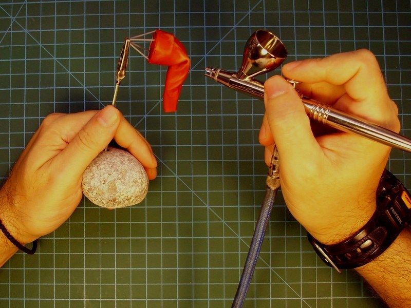
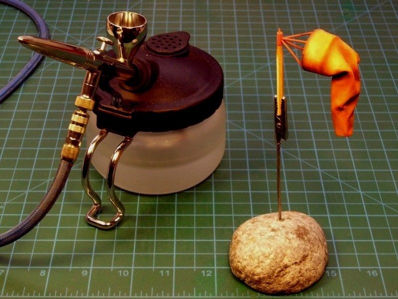
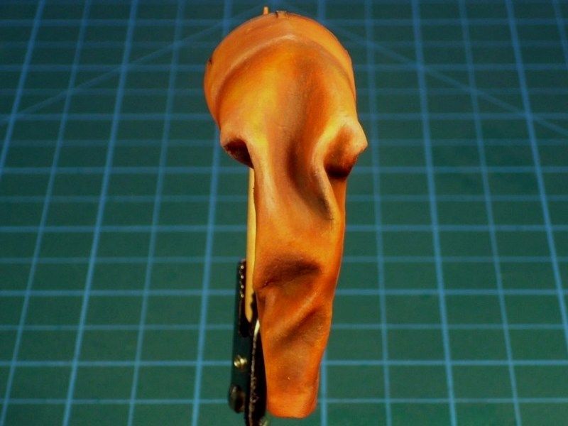
At present time, the windsock is under painting proccess. I used the FS31302 "Matt Red" available by Life Color as LC06 acrylic, applied with a soft brush, to establish a basic layer and later blend it, to look brighter onto the points supposedly lightened more, by spraying much diluted FS30257 "Sand Yellow RLM79VAR" available by Life Color as UA081 acrylic, just not to look too dull. After the primary painting & lighting stage, I repeatedly sprayed a very diluted mixture of thinner and FS33538 "Yellow RLM 04" available by Life Color as UA140 acrylic, at a ratio of 95% - 5%, over selected areas such as the fabric folding edges and a few other points, that IMHO should look more enlightened
 Düzenleyen Nick_Karatzides - 29/01/2016 Saat 04:53 |
|
|
|
|
|
Nick_Karatzides
Üye
Kayıt Tarihi: 06/06/2009 Aktif Durum: Aktif Değil Gönderilenler: 250 |
Gönderim Zamanı: 13/07/2013 Saat 23:59 |
|
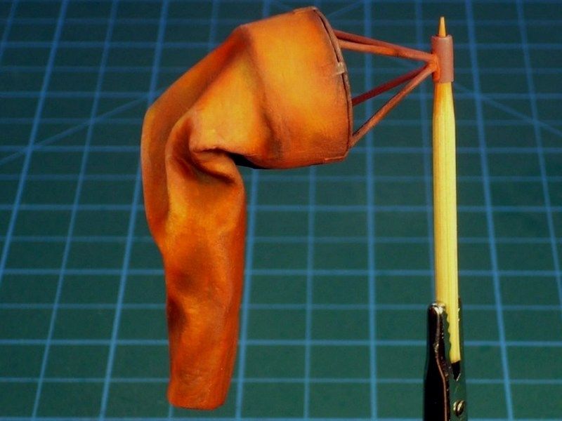
Once the acrylic paint dried, the outcome had tonality differences and looked like been faded by the sun. I had obviously overdone on highlighting the areas and therefore I had to fix this and make the shades softly blend each other. To do so, I mixed artists oil paint "Red" by MIG Productions 502 Abteilung series and artists white spirit by "Winson & Newton in a ratio of 5% / 95% (actually a filter) and sprayed over the windsock. I hope now it looks better than did before.
 Meanwhile I found some time to deal with the green grass. Having a couple of different methods in mind to simulate green grass in scale, I found good idea to follow an old fashioned technique! I planted some grass seeds, watered daily and I'm now expecting to grow high grass soon. Im just kidding of course - watering once every three days, is enough. Kids, dont try this at home. 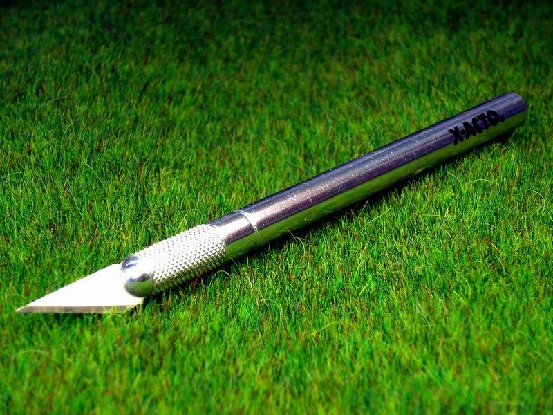 Progress has been slow for various reasons, including:
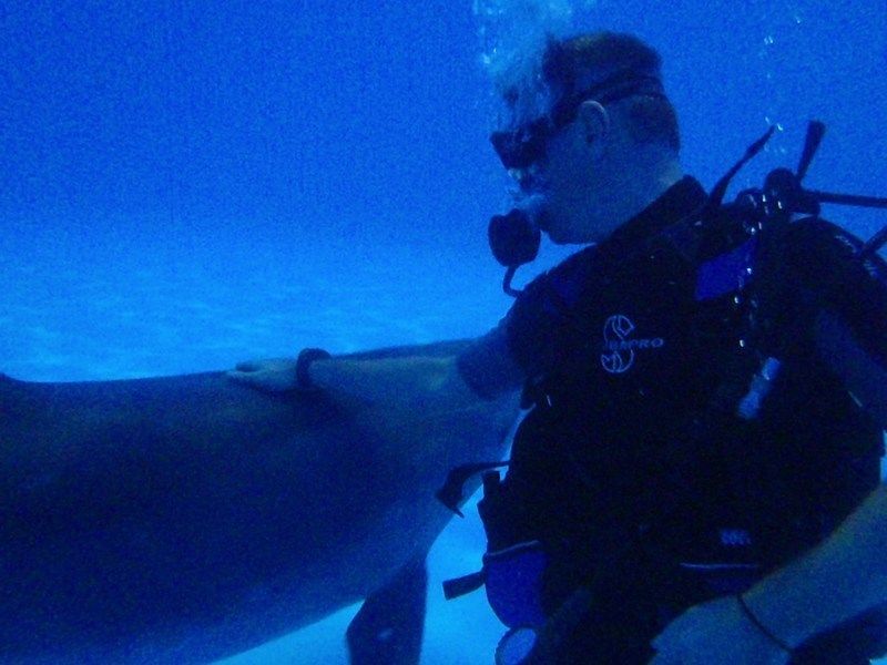
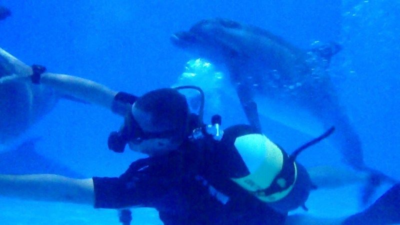
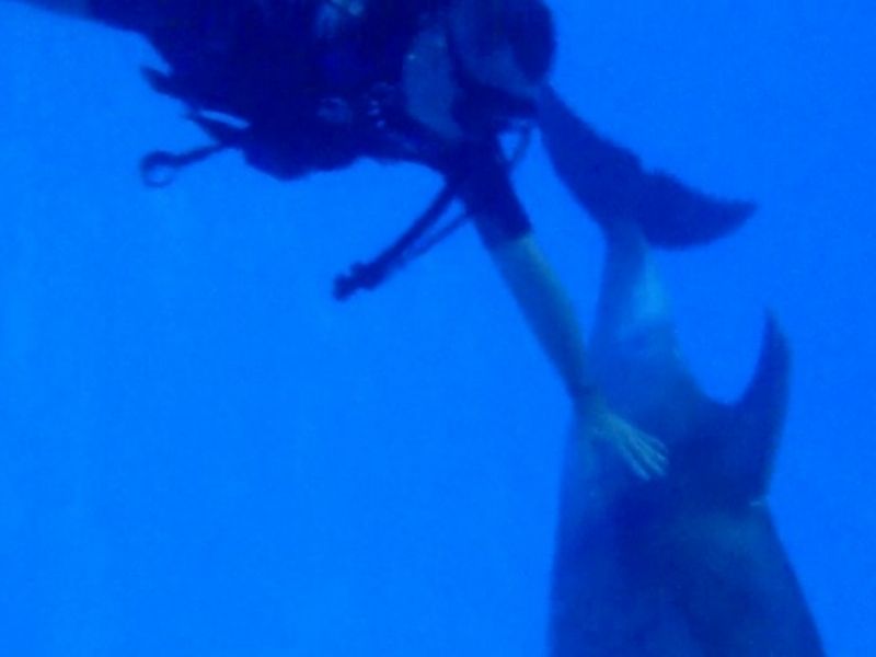
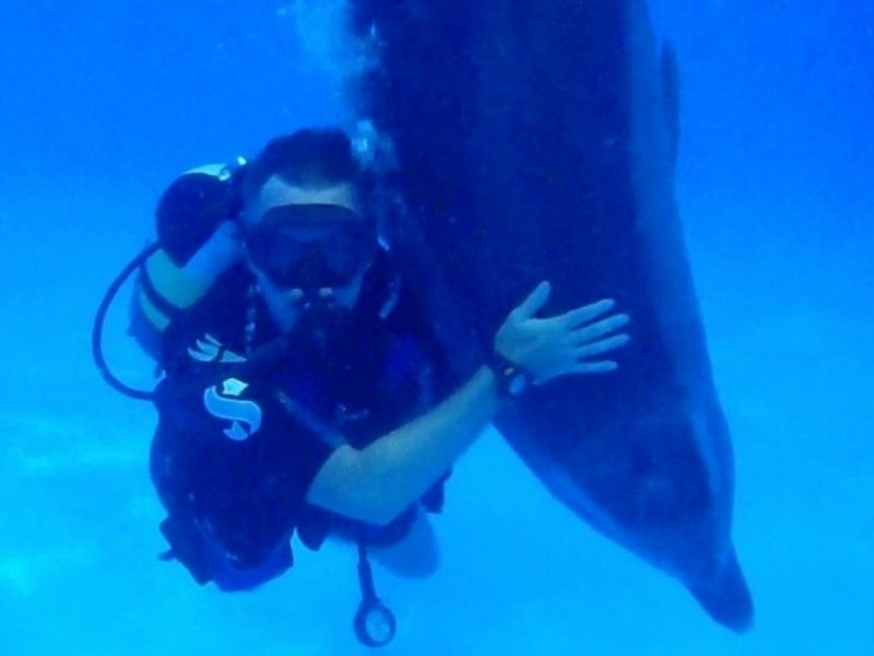
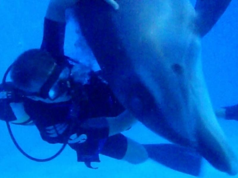
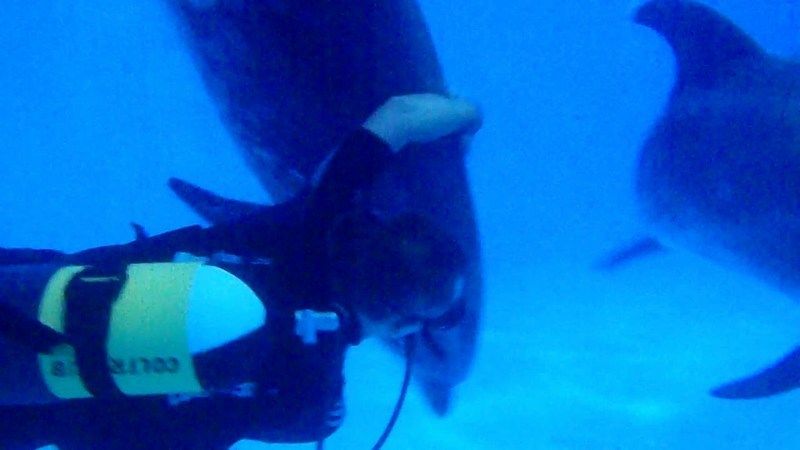
[*]I always find errors and later trying to develop ways to make model look more realistic, [*]Mid-July heat & expectation of upcoming vacations, caused laziness that lead building process to slow down, [*]Wife visits my bench, holding a hammer and that could possibly means that it's about time to quit 1/18 model for a while and give full attention on 1/1 model.  Due to all the above reasons (aka excuses), once the windsock painting process complete, I had to stop for a short relaxing brake and puzzle things out. Next update ETA, late August or early September. Summer is typically the time for vacations and a good chance to relax, unwind & recharge batteries. We all need a break once in a while and I am no exception. I hope you can do the same and enjoy some well deserved time off. I will be back soon, picking up where I left off and complete this project. In the meantime, I plan to unplug, disconnect from anything for a few days, enjoy sunny beaches & crystal waters and hopefully have some SCUBA fun with playful dolphins - as happened last summer. 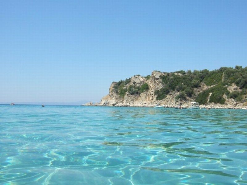
 Düzenleyen Nick_Karatzides - 29/01/2016 Saat 04:55 |
|
|
|
|
|
Nick_Karatzides
Üye
Kayıt Tarihi: 06/06/2009 Aktif Durum: Aktif Değil Gönderilenler: 250 |
Gönderim Zamanı: 12/08/2013 Saat 17:20 |
|
If you followed this WIP during the earlier weeks, you might remember the update few weeks ago, when left home for a much needed vacation to the beach. I am having a difficult time transitioning back from vacation. I had an amazing month living on the beach, playing and soaking in sunshine and honestly I want to still be there instead of writing a new post. It has been less than 24 hours since we arrived home and I can already feel the pull of the day-in-day-out routines. I know that the cat in following picture might looks really silly, but it does capture how truly happy I was on vacation. Transitioning back to reality after vacation, is not easy and I need to get my non-vacation groove back. Any suggestions?
 Düzenleyen Nick_Karatzides - 29/01/2016 Saat 04:55 |
|
|
|
|
|
Nick_Karatzides
Üye
Kayıt Tarihi: 06/06/2009 Aktif Durum: Aktif Değil Gönderilenler: 250 |
Gönderim Zamanı: 13/08/2013 Saat 14:46 |
|
The whole grass field scene would require a 50x40 cm display base, considering that glider measures approx 70 cm wingspan in 1/18 scale. That could be a problem for my show case in home, which yes, it is big, but not big as an elephant. From the MDC - Model Display Cases store, I bought a 50x40 cm base, made of polished beechwood with MDF core.
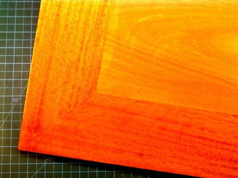 Those who have read my previously uploaded projects, might remember that I prefer using plaster powder to build the section that recreates the ground, especially if it is asphalt. However, the 50x40 cm dimensions of the scene dictate plaster quantity more (and therefore heavier) than usual and for this reason I chose to use another material, because my goal was to build a grass field display base instead of weightlifting equipment for champs. For this reason, I purchased a 50x40 cm size & 10 mm thick sheet of balsa wood from my local hobby shop, which I cut & shaped around with my cheaper than dirt Black & Decker 400 W / 3000 spm jigsaw bought for 20 only. The basic idea, is to produce a thick & flat surface which protrudes approx 10 mm beyond the polished beechwood base, on which later green grass & extra stuff will be added where is needed. 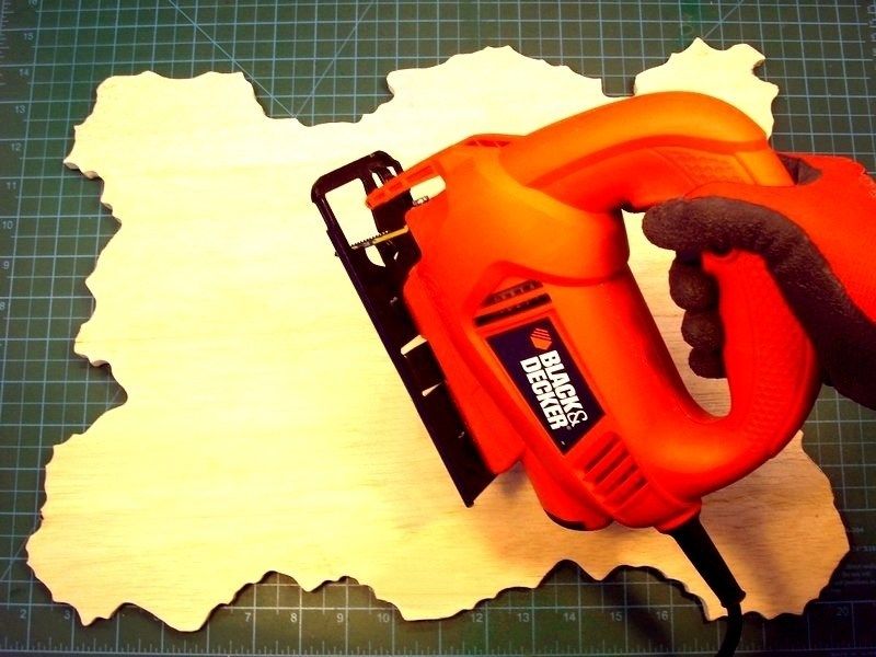
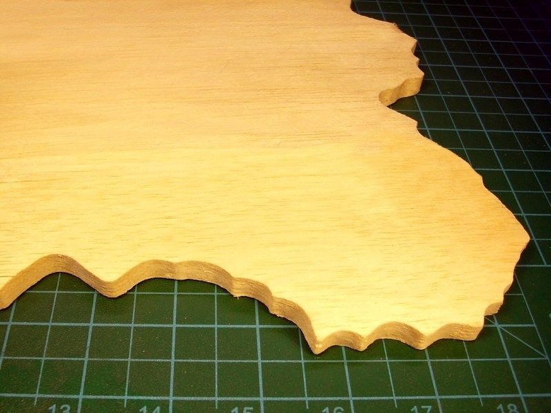
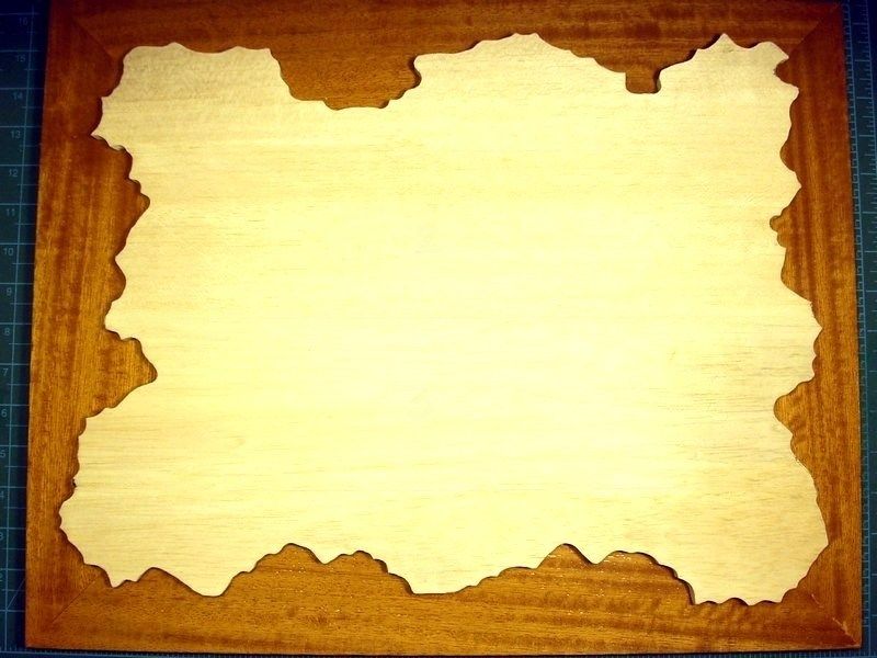 Remember that operating a freehand held jigsaw could be a bad idea if not pay attention on job. Sawdust may also cause problems when breath or shallow. A powerful vacuum system to suck away the dust should be used all time to keep the workbench area clean. Using a breathing mask & pair of protection glasses to prevent dust contact with lungs & eyes, is also an important matter that you should seriously take care of. My recommendation is to also wear working gloves - made of kevlar if possible. 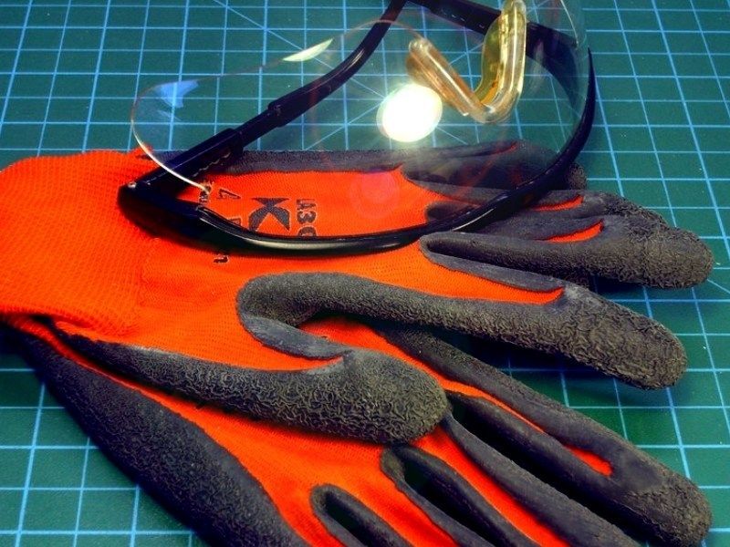 Düzenleyen Nick_Karatzides - 29/01/2016 Saat 04:56 |
|
|
|
|
|
Nick_Karatzides
Üye
Kayıt Tarihi: 06/06/2009 Aktif Durum: Aktif Değil Gönderilenler: 250 |
Gönderim Zamanı: 15/08/2013 Saat 12:37 |
|
Unlike the regular practice followed in my previous projects, in which I glued static grass & plants directly on ground untill filling the whole area, I decided to change for an easier and more appropriate method, taking into account the increased surface to be covered. To do so, I bought a 50x40 cm size green grass carpet, made by Busch which specializes mostly in train dioramas. The green grass carpet will be glued on the 10 mm thick sheet of balsa wood and will become the main substrate of a dense grass covered ground. Later, I plan to add more static grass & plants, to avoid the monotonous flat football field alike green pattern and make it look closer to reality.
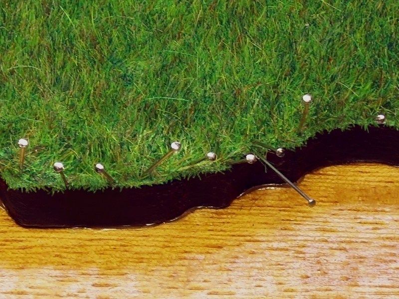
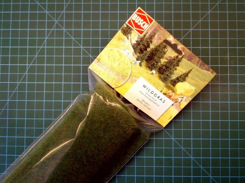 Using scissors, I cut around the Busch's grass carpet, according to contour of the 10 mm thick balsa wood sheet. The grass carpet was secured in place with steel pins and glued onto balsa using water based white glue for wood, which becomes transparent when it dries. Once the process complete and the glue dried, the steel pins which kept the grass carpet nailed on balsa sheet, were carefully removed. 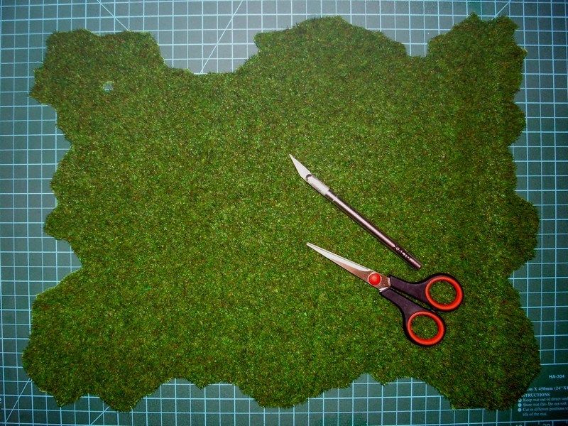

 Düzenleyen Nick_Karatzides - 29/01/2016 Saat 04:57 |
|
|
|
|
| Sayfa 2 Sonraki >> |
| |
||
Forum Atla |
Kapalı Foruma Yeni Konu Gönderme Kapalı Forumdaki Konulara Cevap Yazma Kapalı Forumda Cevapları Silme Kapalı Forumdaki Cevapları Düzenleme Kapalı Forumda Anket Açma Kapalı Forumda Anketlerde Oy Kullanma |
|
